
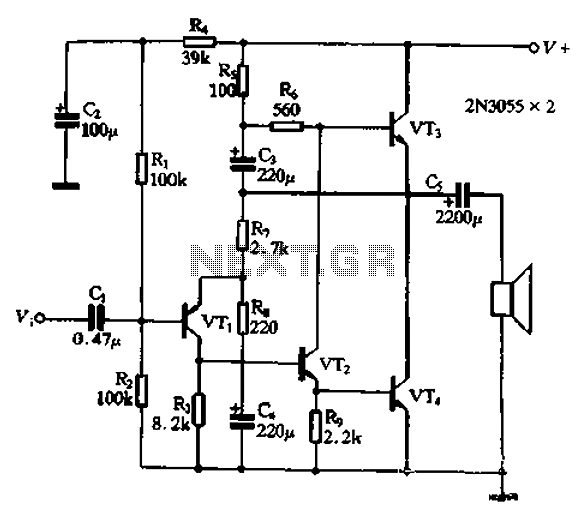
4 Watt audio Amplifier

The circuit described utilizes Darlington output transistors, specifically the TIP41, which are configured to provide a high output current sufficient for driving a 3-ohm speaker. This configuration allows for a robust amplification of audio signals, making it suitable for various applications, including integration with computer audio outputs and cassette deck line outputs. The pre-set gain feature enhances the circuit's versatility, accommodating different input levels effectively.
The PCB dimensions are compact, measuring 60mm x 75mm and a height of 30mm, with the potential to reduce the depth to 10mm by relocating the output capacitor and adjusting the positioning of the electrolytic capacitors. This design consideration allows for a more streamlined installation in various enclosures.
Performance characteristics indicate that the amplifier can operate effectively on a 13.8-volt supply while driving a 3-ohm load. Under normal operating conditions, there is no requirement for extensive heatsinking of the output transistors, although a small heatsink is recommended for continuous operation at high output levels to prevent thermal overload. The thermal management can be simplified by directly bolting the heatsink to the TIP41 transistors, provided there is no risk of electrical contact with other components.
The circuit exhibits stability across the audio frequency range and up to 150 kHz, eliminating the need for additional stability networks like a Zobel network. However, it is noted that increasing the gain may introduce higher distortion and noise levels. Testing has demonstrated satisfactory performance with a gain setting of Vgain = 10 while driving a 3-ohm car Hi-Fi speaker. The use of higher-impedance speakers may result in a broader frequency response, albeit with a slight reduction in output power.
Overall, this amplifier circuit presents a practical solution for audio amplification needs, particularly in compact applications, and is designed with readily available components, making it an accessible project for enthusiasts and professionals alike.The circuit is very simple and incorporates darlington output transistors that will provide more than enough output current than is needed to drive a 3-ohm speaker. The gain may be pre-set for a variety of input levels, making it suitable for amplifying computer and cassette-deck Line-output levels.
The input level is also suitable for use with the TDA7000 receiver. All components are easily available and I will shortly be making this project available as a kit. Naturally, the project will be built on a PCB which will also be available separately. Here is the first PCB, assembled and working. The completed unit is 60mm x 75mm and only 30mm deep. The depth could be reduced to 10mm if the output capacitor is mounted at the speaker and the on-board electrolytics are mounted horisontally. Here are the typical performance figures that may be expected from the finished amplifer using a 3-ohm load with a 13.8-volt supply.
No heatsinking is required for the output transistors when running at a modest output level with either speech or music. A small heatsink should be fitted to the two TIP41 transistors if running a constant tone level. The heatsink could be bolted directly to the TIP41s without electrical isolation if the heatsinks are not going to touch anything.
A heatsink with a 15-square surface area is all that is required. Here is the circuit of the amplifer. The distortion and noise levels may increase at higher gain levels, but the test board was measured with Vgain = 10 and was driving a 3-ohm car Hi-Fi speaker. With higher-impedance speakers the frequency response will become wider but the output power will reduce a little.
There was no trace of instability throughout the AF range and up to 150KHz so I thought it unncecssary to include a Zobel network. Incidentally, four-watts of AF will have the wife banging on the workshop walls, so do not underestimate QRP AF!
🔗 External reference
Related Circuits
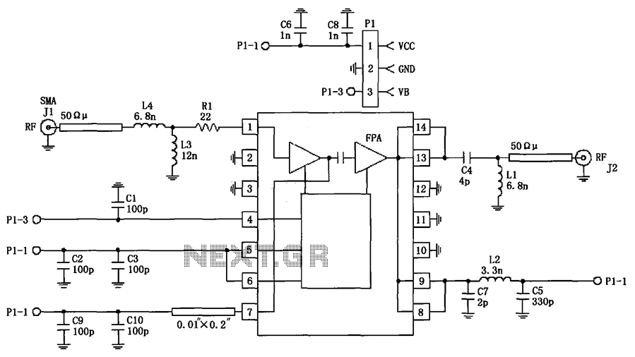
The circuit illustrated in FIG consists of the RF2103P 915MHz RF amplifier circuit. P1 serves as the outlet, where P1-1 connects to power Vcc, P1-2 connects to ground, and P1-3 is used for the power down control voltage VB....
This original design is a variation on a well-known design, examples of which can be found in a great many texts. My variation was to add a second differential stage to replace the usual common emitter-plus-constant current source. Doing...
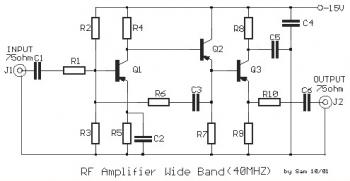
This is a 40 MHz RF amplifier circuit. The sensitivity of a receiver can be significantly enhanced by integrating this circuit between the receiver and the antenna. The amplifier does not utilize resonant circuits and is suitable for both...
The UTC L2572 is a wideband PLL FM demodulator designed primarily for use in satellite tuners. It incorporates all essential components, except for the loop feedback elements, to create a complete PLL system capable of operating at frequencies up...
A wideband transmission or communication channel consists of a broader bandwidth than a single voice channel, utilizing a carrier wave of a specific modulated frequency. This allows for the transmission of more information than narrowband systems, but less than...
The circuit illustrated in Figure 240 is straightforward, utilizing only four transistors to process the input voltage, resulting in a large, inverted output. This configuration serves as a high-performance amplifier, delivering excellent high-fidelity power discharge capabilities. The input stage...