
Incandescent LED Circuit

The described circuit utilizes a 555 timer IC configured in an astable mode to create a pulse-width modulation (PWM) signal that controls the brightness of light-emitting diodes (LEDs). The 555 timer operates by generating a square wave output, which can be adjusted in frequency and duty cycle through external resistors and capacitors.
In this application, the circuit is designed to simulate the gradual dimming and brightening effect characteristic of incandescent lamps, providing a more visually appealing lighting experience. The output from the 555 timer is connected to the anodes of the LEDs, while the cathodes are grounded.
To achieve the desired effect, the timing components (a resistor and a capacitor) must be selected carefully. The resistor values will influence the charge and discharge times of the capacitor, which in turn affects the frequency of the PWM signal. A larger capacitor will result in a slower charge and discharge cycle, leading to a more pronounced fading effect.
To further enhance the performance, a low-pass filter can be employed at the output to smooth out the PWM signal, reducing flicker and creating a more uniform light output. This can be achieved by adding a capacitor in parallel with the LEDs, which will help to maintain a steady current flow during the off periods of the PWM cycle.
Overall, the circuit effectively mimics the warm glow of incandescent lighting by providing a controlled and gradual change in brightness, making it suitable for applications where aesthetic lighting is desired.This circuit when used with a 555 timer will cause light emitting diodes to turn on and off more slowly. This will make the LEDs appear similar to incandescent lamps. 🔗 External reference
Related Circuits

This design aims to restore the classic style of telephones that utilized a pair of gongs to signal an incoming call, evoking a sense of nostalgia with the familiar sound of ringing bells. Presented here is a "Telephone Ring...
The figure illustrates a simple project schematic of a metronome. A metronome is a device utilized by musicians to produce continuous beats through a speaker. The metronome circuit typically consists of several key components that work together to generate a...
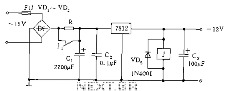
The figure below illustrates the use of a relay in the starting circuit. The power input connects through a resistor R, which serves two purposes: first, it prevents a large current from the capacitor C1 from affecting the power...
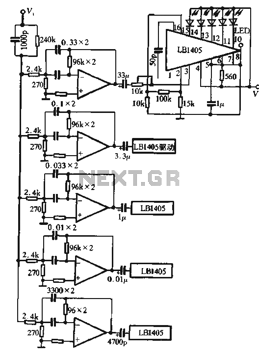
The circuit utilizes the LM324 as a band-pass filter and the LB1405 as a driver for a five-band spectrum display. The selected frequency harmonics are centered at 100 Hz, 330 Hz, 1 kHz, 3.3 kHz, and 10 kHz. The...
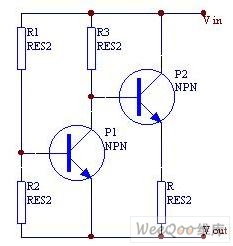
When the current is below the specified threshold, the bias current supplied by resistor R1 causes transistor P3 to saturate and conduct. In this state, it is unable to regulate the current effectively. Conversely, when the current reaches or...
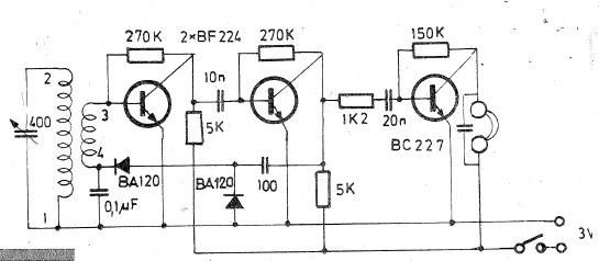
Oscillating circuits (coils) are constructed on a ferrite bar. For long wave reception, winding "1-2" consists of 135 turns, while winding "3-4" has 20 turns. For medium wave reception, winding "1-2" has 75 turns, and winding "3-4" has 7...