
10A stabilized power supply

The circuit described is a high-current power supply capable of delivering a stabilized output of 10A, utilizing a linear voltage regulator from the 78xx series. The 78xx series includes various voltage regulators that can provide different output voltages, thus allowing for flexibility in design based on the required output. The input voltage to the regulator must exceed the desired output voltage by a sufficient margin to ensure proper regulation.
The power handling capability of the circuit is enhanced by the inclusion of a power transistor (T1), specifically the MJ15004, which is a high-power NPN transistor. This component is crucial for managing the increased current demands and should be mounted on a substantial heat sink to dissipate heat effectively, especially under high load conditions. The heat sink is necessary to prevent thermal overload and ensure reliable operation of the circuit.
Resistors R1 and R2 are specified as 0.18 ohms with a power rating of 5W, which suggests they are likely used for current sensing or as part of a feedback loop to stabilize the output. R3, with a value of 2.2 ohms and a power rating of 2W, could be used for additional current limiting or as part of a voltage divider configuration.
Capacitors C1, C2, and C3 are integral to the circuit's performance. C1, with a capacitance of 22000 µF, acts as a bulk filter capacitor, smoothing the output voltage and providing energy storage to handle transient loads. C2 and C3, both rated at 1 µF, are likely used for high-frequency decoupling, ensuring stable operation of the regulator by filtering out noise and providing a clean power supply.
The circuit also includes a fuse (B1) rated at 35A, which serves as a protective measure against overcurrent conditions, safeguarding both the circuit and connected loads.
Overall, this heavy-duty power supply circuit is designed for applications requiring significant current, with careful consideration given to thermal management, filtering, and protection to ensure stable and reliable operation.This is a heavy diet, which can deliver 10A stabilized. The circuit is built around a normal 78xx controller, but for extra power equipped with T1. For the 78xx can be taken any type. Keep in mind that the input voltage of 3V regulator must be higher as the output nected. See 78xx power for the available controllers. T1 must be a large heat sink mounted when large capacities are diminished. A negative variant of this diet is here to find. R1, R2 = 0.18 ? 5W R3 = 2.2 ? 2W C1 = 22000?F C2, C3 = 1?F B1 = 35A T1 = MJ15004 IC1 = 78xx 🔗 External reference
Related Circuits
The phone company provides 3 levels of power. With no devices 'off hook' the line rests at 48 volts DC. If you draw any more than a fraction of a milliamp or so, you get the phone company's attention...
A stabilized voltage inverter that converts 12V to 220V with a power rating of 200W is illustrated in the accompanying diagram. This inverter can utilize an existing dual 12V-200W mains transformer; however, it exhibits low inverter efficiency. The described stabilized...
The LM317 is capable of providing extremely good load regulation, but a few precautions are needed to obtain maximum performance. For best performance, the programming resistor (R1) should be connected as close to the regulator as possible to minimize...
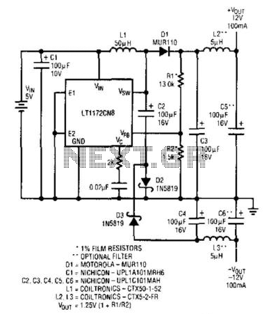
An LT1172 generates positive and negative voltages from a 5-V input. The LT1172 is configured as a step-up converter. To generate the negative output, a charge pump is used. C2 is charged by the inductor when D2 is forward-biased...
12W Audio Power Amplifier Circuit Diagram. Features: small power amplifier, excellent sound quality, incorporates a fully integrated design. The 12W audio power amplifier circuit is designed to provide high-quality audio amplification in a compact form factor. This amplifier is capable...
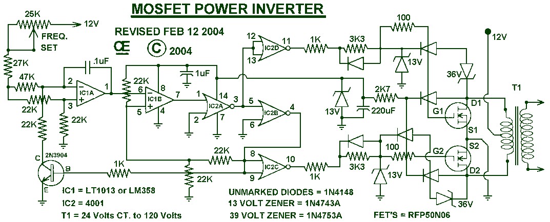
1000W Power Inverter circuit diagram: This is a power inverter circuit based on the MOSFET RFP50N06. The inverter is capable of handling loads up to 1000W, depending on the specifications of the transformer used. The RFP50N06 MOSFETs are rated...