
Stabilized voltage inverter 12V-220V 200W

The described stabilized voltage inverter is designed to convert a low-voltage DC input of 12V into a higher-voltage AC output of 220V, suitable for powering standard household appliances. The inverter operates at a rated power of 200W, making it applicable for various low to medium power applications.
The core component of this inverter is a dual 12V-200W mains transformer, which plays a crucial role in stepping up the voltage. The transformer is configured to handle the input from a 12V DC source, which can be supplied by batteries or other DC power sources. The inverter circuit typically includes a switching mechanism, often employing transistors or MOSFETs, to create an AC waveform from the DC input.
The efficiency of the inverter is a critical parameter, as it determines how much of the input power is converted into usable output power. In this case, the inverter is noted for having low efficiency, which may be attributed to factors such as switching losses, transformer losses, and other components in the circuit that contribute to energy dissipation.
To improve performance, it may be beneficial to explore advanced circuit topologies or components that enhance efficiency, such as using high-frequency switching techniques or optimizing the transformer design. Additionally, implementing feedback mechanisms can help stabilize the output voltage and improve overall inverter performance.
The schematic diagram accompanying the description would typically include key components such as the transformer, switching devices, capacitors for filtering, and possibly an output stage to refine the AC waveform. Proper design considerations must also include thermal management to ensure the components operate within safe temperature limits during extended use.
Overall, while the inverter provides a functional solution for voltage conversion, attention to efficiency improvements and circuit optimization can significantly enhance its performance.Stabilized voltage inverter 12V-220V 200W is shown in the following diagram. It can adopt existing dual 12V-200W mains transformer. But its invert efficiency is low.. 🔗 External reference
Related Circuits
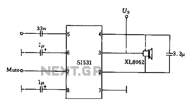
The battery voltage is 1V for a low-frequency amplifying circuit, which can operate with a power supply voltage ranging from 1V to 1.7V, making it suitable for use with small batteries. The circuit provides an output power of 80mW...
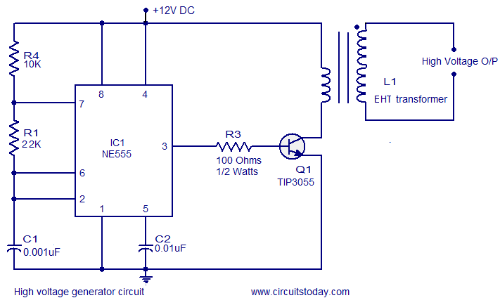
This circuit is highly dangerous due to its output voltage, which is in kilovolts and poses a significant risk of serious injury or death. It should only be attempted by individuals with extensive experience in handling high voltages. No...
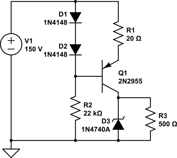
A simple low voltage/current power supply that can accept a wide range of input voltages, up to several hundred volts. The input range is specified as 20 to 160V DC, with an output requirement of 10V and a maximum...
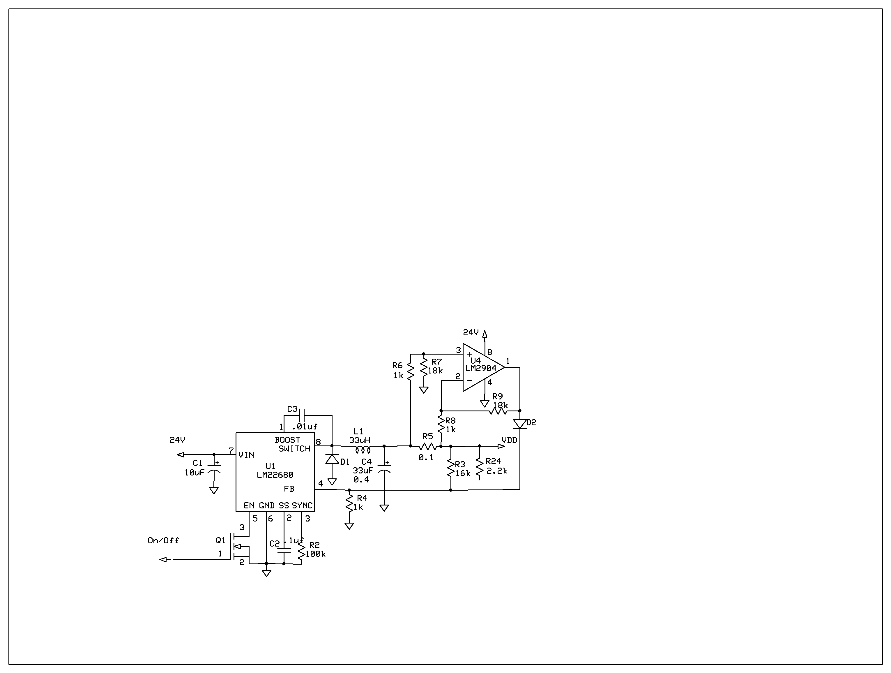
The product requires a voltage-controlled, current-limited power supply. Various switcher chips have been used with an op-amp to provide feedback for a current sense voltage to the feedback pin. Currently, an LM22680 is in use, but it has shown...
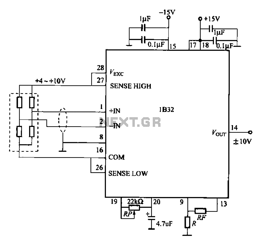
The circuit for bridge measurements is straightforward, as illustrated in the figure. The sensor bridge drive voltage can be adjusted between +4V and +10V, depending on the specific requirements of the sensor. Two fixed gain options of 333.3 and...
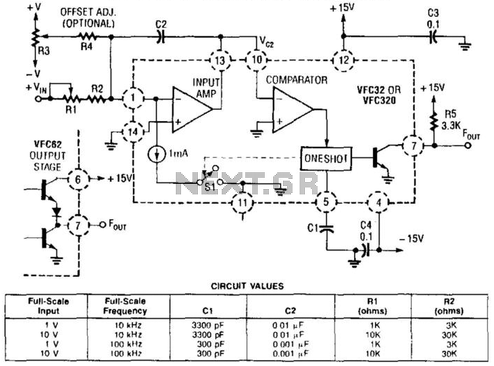
This voltage-to-frequency converter utilizes a Burr-Brown VFC 32 integrated circuit (IC) and requires minimal components. The circuit values are illustrated in the accompanying figure. This charge-balanced voltage-to-frequency (V/F) converter employs either a VFC32 or a VFC320 IC. The positive...