
10MHZ to 1MHz converter

The described circuit functions as a 10 MHz oscillator utilizing integrated circuits (ICs) for generating and dividing frequency signals. The primary components include two oscillator stages represented by IC1A and IC1B, which are configured to produce a stable 10 MHz signal. The design leverages the properties of these ICs to achieve the desired frequency output effectively.
The frequency divider, denoted as IC2, plays a crucial role in reducing the output frequency from 10 MHz to 1 MHz. This division is accomplished through a binary counting mechanism, where the input frequency is divided by a factor of ten. The output from IC2 is taken from pin 12, providing a clean and stable 1 MHz signal suitable for various applications.
In addition to the frequency generation and division, the circuit incorporates a buffer stage using IC1C. This buffer serves to isolate the oscillator and divider stages from any load effects that could distort the frequency output. By providing a high input impedance and low output impedance, the buffer ensures that the integrity of the signal is maintained throughout the circuit.
A variable capacitor, rated at 39 pF, is included in the design for microtuning the frequency. This component allows for fine adjustments to be made to the oscillator frequency, enabling precise control over the output signal. The tuning capability is essential in applications where frequency accuracy is critical.
The overall design is characterized by its simplicity and reliability, as it does not require any external adjustments for operation. This feature makes the circuit particularly suitable for use in applications where consistent performance is essential, such as in communication systems, signal processing, and frequency reference generation. The integration of these components into a cohesive circuit ensures that the oscillator can deliver stable and precise frequency outputs with minimal intervention.This circuit is an oscillator at frequency 10MHZ, using IC 1A and IC1B and a frequency divider. Using the IC2 it divides the pulses to 10. IC1C is a buffer. The variable capacitor 39pF is microtunig the frequency . The pin 12 of the IC2 is the output, where we can have the 1 MHz . The circuit does not need any adjustments to work. 🔗 External reference
Related Circuits
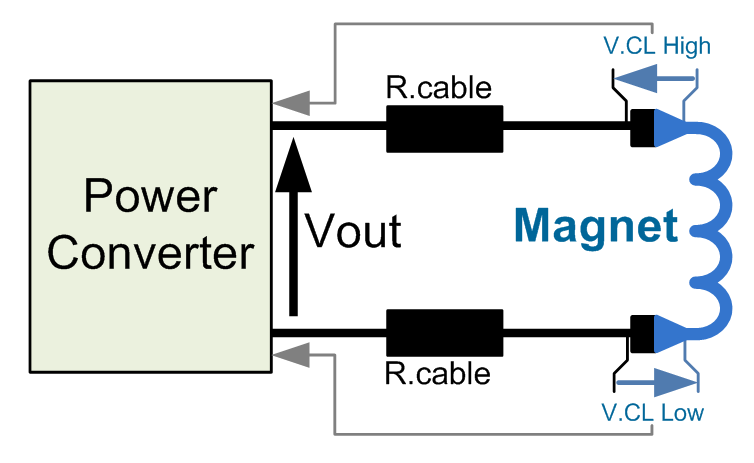
This power converter is utilized in the LHC machine to supply power to superconductive magnets. It is situated in the underground installation of the LHC, in proximity to the loads to minimize cable losses. The voltage source employs a...
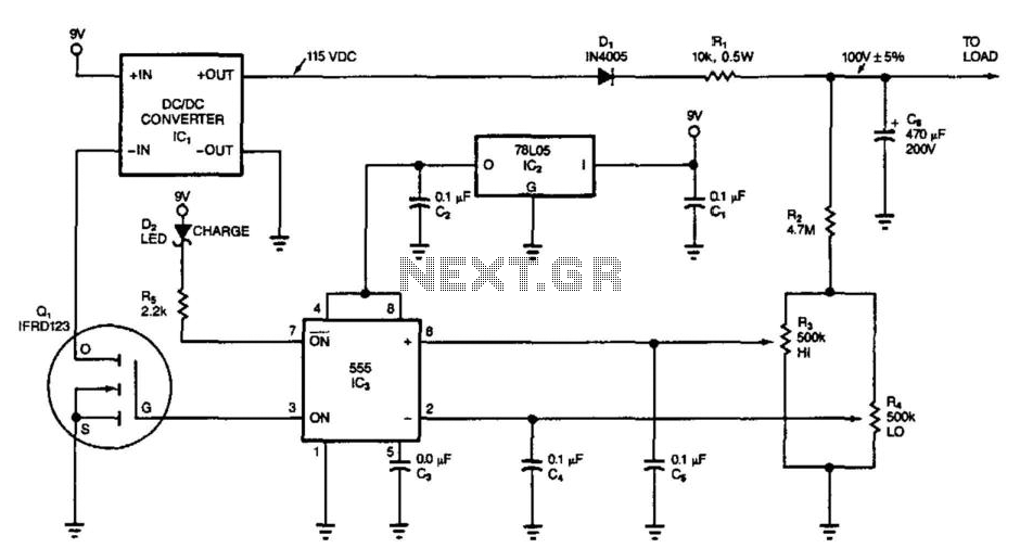
This circuit switches its DC/DC converter, IC1, off whenever the large filter capacitor, C6, has sufficient charge to power the load. This particular circuit uses a DC/DC converter that produces 115 Vdc from a 9 Vdc input; it can...
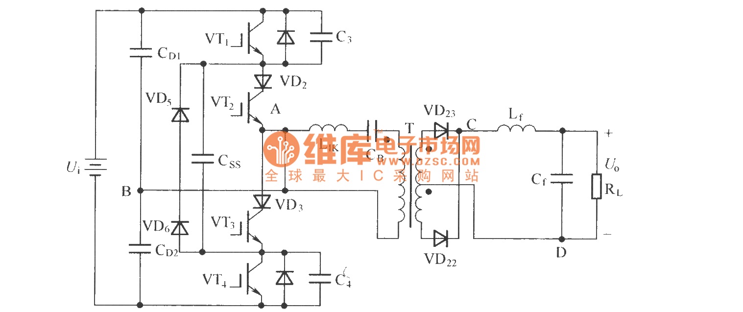
To eliminate circulating current in a zero-voltage switch three-level DC converter during its zero state, a zero-voltage zero-current switch three-level DC converter circuit has been proposed. The primary distinction between this circuit and the standard zero-voltage switch three-level DC...
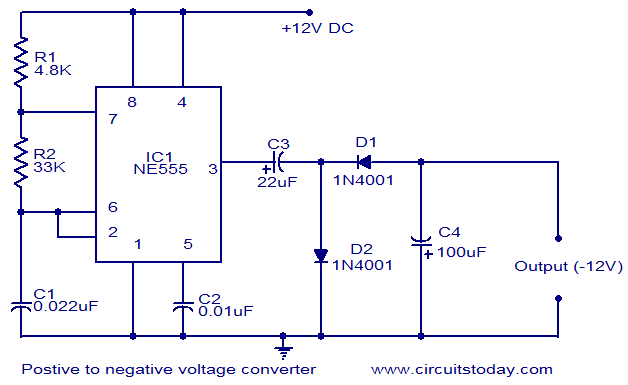
This circuit diagram illustrates the method for obtaining a negative voltage from a positive voltage supply. An additional benefit of this circuit is that the negative voltage, combined with the original positive supply, can be used to simulate a...
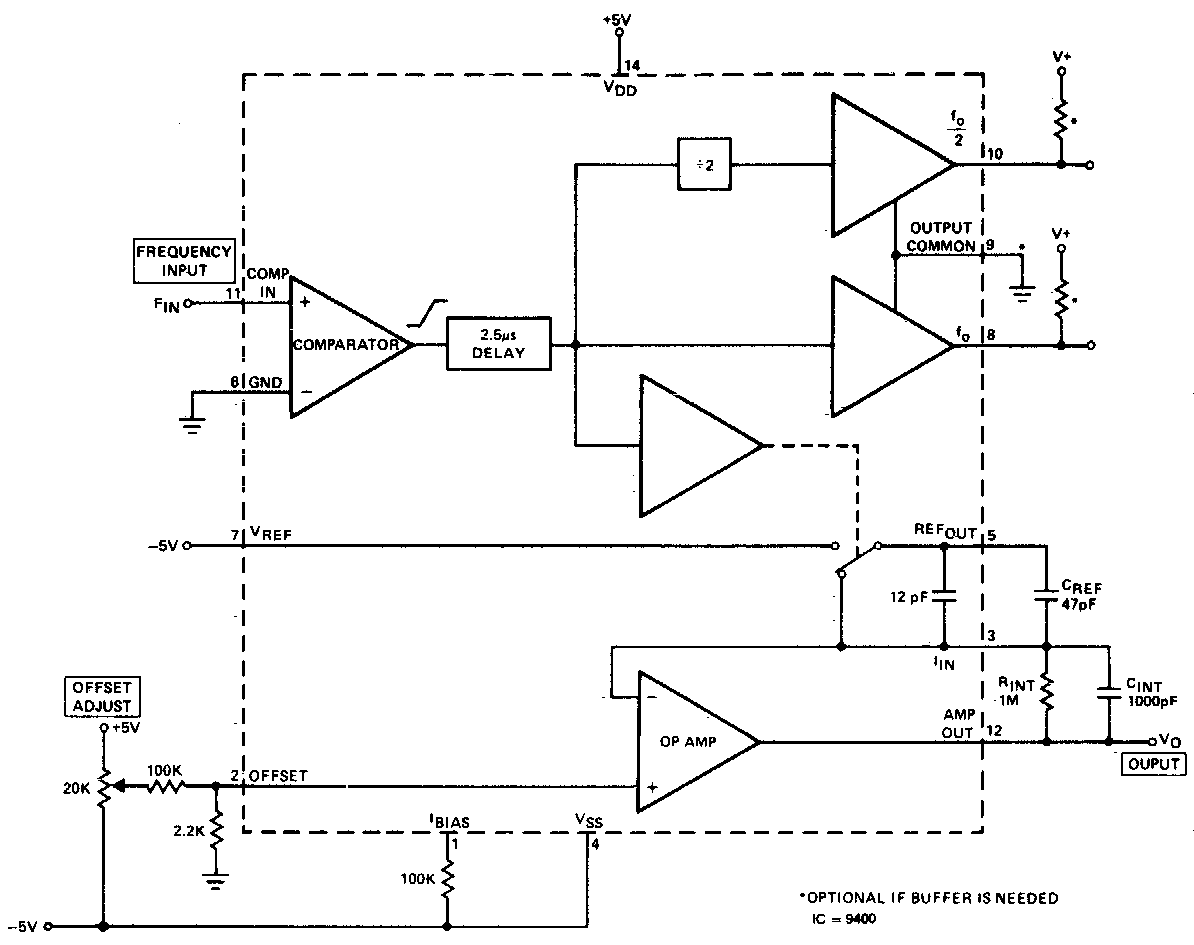
The converter produces an output voltage that is linearly proportional to the input frequency waveform. Each zero crossing at the comparator's input results in a specific change being dispensed into the op-amp's summing junction. This charge subsequently flows through...

The circuit is designed to convert sinusoidal input signals into TTL output signals and can process input voltages exceeding 100 mV. This circuit typically employs a comparator to achieve the conversion from sinusoidal to TTL levels. The sinusoidal input signal...