
DC-10Khz frequency-voltage converter

The described circuit functions as a frequency-to-voltage converter, which is a crucial component in various applications such as signal processing and instrumentation. The core of the design includes a comparator that detects zero crossings of the input frequency waveform, which is typically a square wave or sinusoidal signal. Upon each zero crossing, the comparator outputs a pulse that triggers a precise charge injection into the summing junction of the operational amplifier (op-amp).
The op-amp, configured in a summing amplifier mode, accumulates these injected charges over time. The feedback resistor connected to the op-amp plays a vital role in determining the gain of the circuit, thereby influencing the amplitude of the output voltage. As the frequency of the input signal varies, the rate at which the zero crossings occur changes, leading to a corresponding variation in the output voltage.
A key component of the circuit is the integration capacitor (Cint), which is placed in parallel with the resistor (Rint). This capacitor serves to smooth out the voltage pulses generated at the op-amp output, effectively averaging them over time. The time constant defined by the product of Rint and Cint determines the response time of the circuit, allowing it to accurately reflect the input frequency as a stable DC voltage.
In summary, this frequency-to-voltage converter operates by utilizing a comparator to detect zero crossings, an op-amp to integrate the resulting pulses, and a capacitor to average the output, ensuring that the final DC voltage output remains linearly proportional to the input frequency. Such circuits are widely used in frequency measurement applications, analog signal processing, and in systems where frequency needs to be converted to a usable voltage level for further processing or display.The converter generates an output voltage which is linearly proportional to the input frequency waveform. Each zero crossing at the comparator`s input causes a precise amount of change to be dispensed into the op amp`s summing junction.
This charge in turn flows through the feedback resistor generating voltage pulses at the output of the op ampCapacitor (Cint) across Rint averages these pulses into a dc voltage which is linearly proportional to the input frequency 🔗 External reference
Related Circuits
I had a Basic Stamp project that needed to measure a nominal 12 volt battery, and I wanted a simple solution. This is the simplest I could come up with. The 555 timer will put out positive pulses. The...
The circuit diagram depicts a design that achieves 0.25% exponential conformity over a frequency range of 20 Hz to 15 kHz using a single LM392 and an LM3045 transistor array. The exponential function is generated by Q1, whose collector...
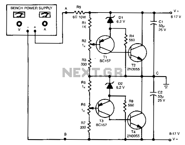
The outputs in this circuit are independently variable and can be loaded unsymmetrically. The output voltage remains constant, regardless of load and changes. By varying potentiometers R2 or R6, the output voltages can be conveniently set. Outputs can be...
This circuit diagram illustrates the design of a straightforward AC voltage converter that transforms 240V AC power into 110V AC. The circuit can effectively be utilized to power electrical devices that necessitate a supply voltage of 110V. The AC voltage...
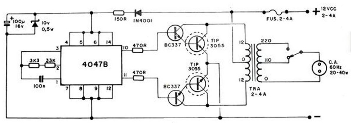
The converter transforms 12 VDC to 220 VAC, allowing for the conversion of 12 volts DC into 220 volts AC. The circuit diagram provided illustrates a simple converter circuit. This DC to AC converter can supply voltage for a...
The circuit was designed to create a frequency converter using a crystal oscillator for the conversion of 10 MHz to 1 MHz. It incorporates a 7404 hex inverter. The circuit functions as a frequency divider, utilizing a crystal oscillator to...