
50mW amplifier schematic

This audio amplifier circuit is designed as a compact and efficient solution for low-power applications, resembling the architecture commonly found in small transistor radios. The circuit employs a differential input stage that utilizes complementary output transistors, which are configured to achieve a balanced operation. The biasing of the input stage is accomplished through a clever arrangement where the supply voltage is evenly distributed across the output transistors. This is further enhanced by the inclusion of diodes connected between the bases of the output transistors, ensuring that both devices are slightly biased into conduction, thus improving linearity and reducing distortion.
To maintain stable operation across varying temperatures and component tolerances, a 3.3-ohm resistor is placed in series with the emitters of the output transistors. This resistor plays a crucial role in stabilizing the bias current, ensuring that changes in temperature or differences in component characteristics do not significantly affect the amplifier's performance. As the bias current increases, the voltage drop across the emitter-base junction of the transistors decreases, which in turn reduces the conduction, providing a self-regulating mechanism that enhances reliability.
The amplifier exhibits an input impedance of approximately 500 ohms, making it compatible with a variety of audio sources. With an 8-ohm speaker connected, the voltage gain is around 5, allowing for adequate amplification of audio signals. The output voltage swing across the speaker is about 2 volts, which is sufficient to drive the speaker without introducing distortion, while the power output is in the vicinity of 50 milliwatts. For applications requiring higher power output, increasing the supply voltage and incorporating heat sinks on the output transistors can facilitate greater power handling capabilities.
The circuit operates efficiently, drawing approximately 30 milliamps from a 9-volt supply, making it suitable for battery-powered applications. Overall, this audio amplifier design presents a practical solution for low-power audio amplification needs, balancing performance and efficiency effectively.Here is a little audio amplifier similar to what you might find in a small transistor radio. The input stage is biased so that the supply voltage is divided equally across the two complimentary output transistors which are slightly biased in conduction by the diodes between the bases. A 3.3 ohm resistor is used in series with the emitters of the output transistors to stabilize the bias current so it doesn't change much with temperature or with different transistors and diodes.
As the bias current increases, the voltage between the emitter and base decreases, thus reducing the conduction. Input impedance is about 500 ohms and voltage gain is about 5 with an 8 ohm speaker attached. The voltage swing on the speaker is about 2 volts without distorting and power output is in the 50 milliwatt range. A higher supply voltage and the addition of heat sinks to the output transistors would provide more power.
Circuit draws about 30 milliamps from a 9 volt supply. 🔗 External reference
Related Circuits
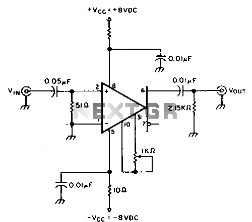
This circuit provides approximately 20 dB of voltage gain with a frequency range from 0.5 to 50 MHz. The low-frequency response of this circuit can be extended by increasing the value of the 0.05 µF capacitor or by removing...
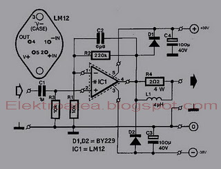
This is an 80W power amplifier OCL circuit that utilizes the integrated circuit LM12. It effectively enhances bass and treble performance. When connected to a CD player, it produces high-quality sound, especially when paired with a good pre-tone control....
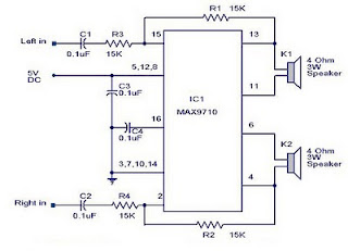
A 3-watt stereo amplifier circuit utilizing the MAX9710 integrated circuit (IC). The MAX9710 is a stereo audio power amplifier IC capable of delivering 3 watts of output to 4-ohm loads. It can operate from a single power supply ranging...
The 13TL amplifier utilizes discrete components and features a complex circuit structure. In contrast, the BTL amplifier circuit structure is simpler and generally performs well with fewer discrete components. Some integrated amplifiers, which are produced on a single integrated...
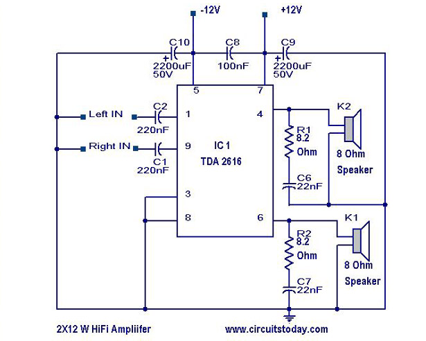
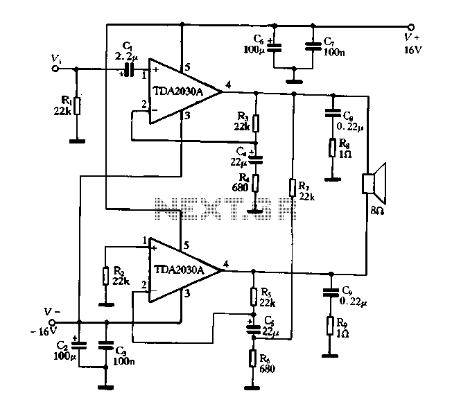
A simple Hi-Fi amplifier circuit diagram with a schematic for creating an audio amplifier, designed using the TDA 2616 integrated circuit (IC), which is a stereo power amplifier. It is suitable for use with radios, tape players, and televisions,...
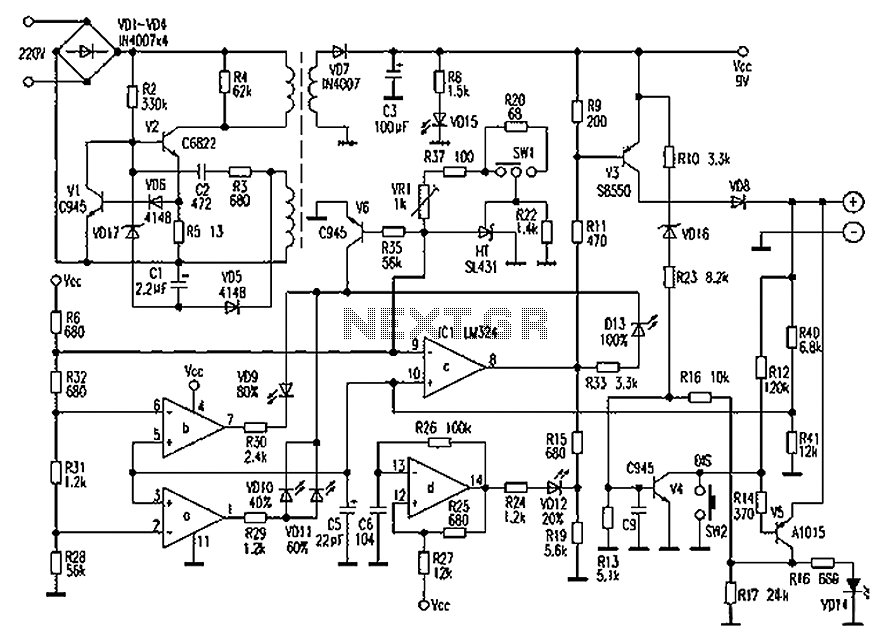
Chaolitong Phone Travel Charger for Motorola models 308, 328, 338, and 368 series mobile phone batteries. This charger features a switch for nickel-cadmium, nickel-hydrogen, and lithium-ion batteries, along with a discharge function. It operates with an AC mains input...