
amplifier LM386 amp circuit lag

The described circuit involves a push-to-talk switch, which is typically used in communication devices to activate a microphone or transmitter. The delay in audio output may be attributed to several factors, including the design of the circuit, the type of switch used, or the components interfacing with the button.
To address the delay, a detailed examination of the circuit is necessary. The push-to-talk switch can be connected to a microcontroller or an audio processing unit that manages the audio signal. When the button is pressed, it should trigger a digital input on the microcontroller, which can then activate an audio output after a defined delay.
Consider implementing a debounce circuit to eliminate any noise generated by the mechanical switch. This can be achieved using an RC (resistor-capacitor) filter or software debouncing in the microcontroller. Additionally, if the audio processing unit has a built-in delay, it may be necessary to adjust the settings or use a faster processing chip to reduce latency.
The circuit schematic should include the push-to-talk switch, a microcontroller, and the audio output stage. The switch connects to a digital input pin on the microcontroller, and the output pin connects to an audio amplifier or speaker. Proper power supply decoupling should also be included to ensure stable operation of the microcontroller and audio components.
In summary, the circuit requires careful consideration of the switch mechanism, the processing unit, and the output stage to minimize the delay and ensure immediate audio feedback upon pressing the button.I`ve got a button which I use as a push to talk switch. This works for the most part, however when I press the button it takes a good 5 seconds before I hear any output. 🔗 External reference
Related Circuits
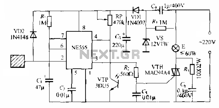
The circuit utilizes a NE553 automatic light sensor composed of 55 groups, allowing lights to turn on when individuals are present and turn off when they leave. The power supply includes VD1, vS, and C, with a 12V DC...
The circuit utilizes a 555 timer configured as a multivibrator, where the oscillation frequency is determined by resistors R1, R2, and capacitor C1. The frequency formula is given by fo = 1.443 / ((R1 + R2) * C1). The...
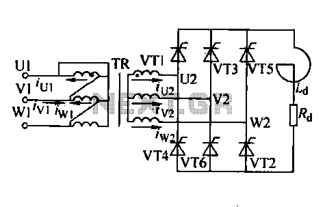
Trigger circuit routing forms include various types such as simple trigger circuits, single-junction transistor trigger circuits, synchronous sine wave trigger circuits, sawtooth transition phase shift (synchronous) trigger circuits, and integrated trigger circuits. This section presents individual cases for introduction...
The 555 timer is utilized as a clock source to drive the RS7490 decimal counter, providing a BCD output to a 7-segment LED display. The clock frequency can be adjusted by changing the value of resistor R1. The circuit operates...
This mini audio amplifier will test the audio stages in amplifiers such as the front end of FM bugs. You can also use it on lots of our other projects as well as the output stages of radios. It...
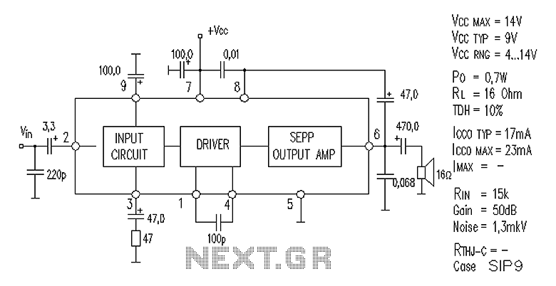
AN7112 power amplifier circuit diagram The AN7112 is a power amplifier designed for audio applications, capable of delivering high output power while maintaining high fidelity. The circuit diagram typically includes essential components such as transistors, resistors, capacitors, and a...