
Audio Clipping Indicator

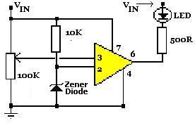
The clipping detection circuit is designed to monitor audio signals in various electronic devices such as preamplifiers, mixers, and amplifiers. It serves the essential function of indicating when the audio signal level exceeds the maximum allowable limit, which can lead to distortion. The circuit utilizes a single LED as a visual indicator of clipping, illuminating when the signal surpasses the defined threshold.
The circuit's power supply is provided by a 9V battery, ensuring portability and ease of use in various settings. The LED display is strategically placed for easy visibility, allowing users to quickly ascertain the status of the audio signal. The design of the circuit includes a comparator or an operational amplifier configured to compare the input signal against a reference voltage. When the input signal exceeds this reference level, the output of the comparator activates the LED.
The components typically involved in this circuit include resistors to set the reference voltage, capacitors for signal coupling, and possibly a diode for protecting the LED from reverse polarity. The configuration can be adjusted depending on the specific application requirements, such as sensitivity to clipping and response time.
Overall, this circuit provides a straightforward solution for monitoring signal integrity in audio equipment, helping to prevent distortion and maintain sound quality.Detects clipping in preamp stages, mixers, amplifiers etc., Single LED display 9V Battery supply unit This circuit was intended to be used as a separate.. 🔗 External reference
Related Circuits
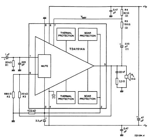
The TDA1514 audio amplifier circuit design is an electronic project capable of delivering high audio power output using a specialized audio integrated circuit (IC) and a few common components. Manufactured by Philips Semiconductor, the TDA1514 audio IC can provide...
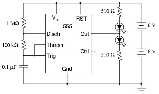
An oscilloscope is useful for analyzing the waveforms produced by this circuit, although it is not essential. An audio detector serves as a valuable piece of test equipment for this experiment, particularly if an oscilloscope is unavailable. The "555"...
The circuit is designed for individuals who spend extensive hours exploring the various resources of this site. Although it comprises only three components, it effectively indicates whether the telephone line has been released after a prolonged connection via modem...
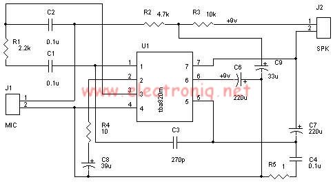
A very simple audio amplifier circuit can be designed using the TBA820M audio amplifier integrated circuit with just a few electronic components. This audio amplifier project features a high gain that allows for the detection of sounds underwater. The...
A simple voltage status monitor built around the LM741 operational amplifier. These circuits are recognized for their accuracy, ease of operation, and cost-effectiveness. The LM741 serves as an operational amplifier, widely used for various applications. The primary function of...
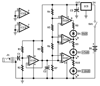
No setup is required: if correct values are used for resistors R3 to R7, LED D1 will illuminate at 0 dB input (0.775V RMS), LED D2 at +5 dB input (1.378V RMS), and LED D3 at +10 dB (2.451V...