
12/24/48 V D.C. Tester

The described tester serves as a versatile tool for diagnosing electrical circuits, particularly in marine applications. It incorporates a simple yet effective design that allows for easy adaptation to various voltage levels through resistor selection. The use of test clips or crocodile clips facilitates secure connections to the voltage rails, ensuring reliable measurements.
The circuit typically consists of a power supply section, LED indicators, and a resistor network. The power supply provides the necessary voltage for the operation of the LEDs and the measurement circuitry. The resistor values play a critical role in setting the voltage range for the tester. By selecting appropriate resistor values, the tester can be configured for 12 V, 24 V, or 48 V systems, thereby enhancing its utility across different applications.
The LED indicators are crucial for providing visual feedback during testing. The red LED signals a positive voltage, while the green LED indicates a negative voltage. This dual-indicator system allows users to quickly assess the voltage status at the test point. In addition to standard voltage testing, the ground-leak testing feature is particularly beneficial in identifying potential safety issues within the electrical system. By detecting leakage to earth potential, the tester aids in ensuring the integrity of the electrical installation.
Overall, this tester is an essential instrument for anyone working with electrical systems in pleasure craft, offering both functionality and adaptability to meet various testing needs.The present tester is intended primarily for testing the 24 V electrical circuits found on most pleasure craft. However, if the resistors are given different values, the circuit may, of course, be used for other voltage ranges.
For 12 V, the value of the resistors should be 1. 2 k, and for 48 V, 4. 7 k. The tester should be connected to the +ve an d ve voltage rails with test clips or crocodile clips, whereupon the test probe is placed on the point to be tested. When the potential at the point is positive, the red LED lights; if it is negative, the green one does.
If the supply is not connected to earth, the tester may be used as ground-leak tester. In this situation, one of the LEDs lights when the test probe touches a point at earth potential and there is a leakage. 🔗 External reference
Related Circuits
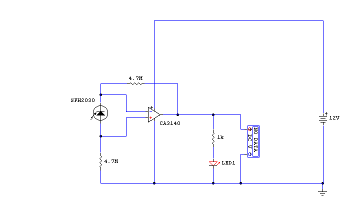
A photodiode, SFH2030, serves as an infrared sensor. A MOSFET operational amplifier, CA3140, is utilized in differential mode to amplify the current pulses from the photodiode. LED1, an ordinary colored LED, illuminates when infrared radiation is detected. The output...

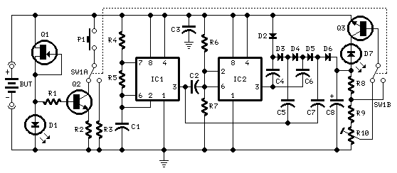
This circuit originated from the necessity for a simple and efficient network tester that could be operated by a single individual. All the commercial units tested required a personal... This network tester circuit is designed to provide a straightforward solution...
Tests 1.5 to 15 Volt cells. This circuit runs a fast battery test without the need of power supply or expensive moving-coil voltmeters. It features two ranges: when SW1 is set as shown in the circuit diagram, the device...
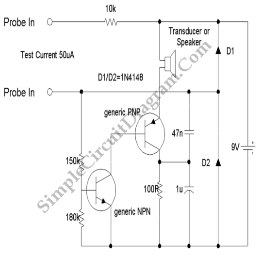
This continuity tester emits a beep sound when it detects electrical current conduction between its probes. Below is the schematic diagram of this audible device. The continuity tester is a simple yet effective tool used to check the integrity of...
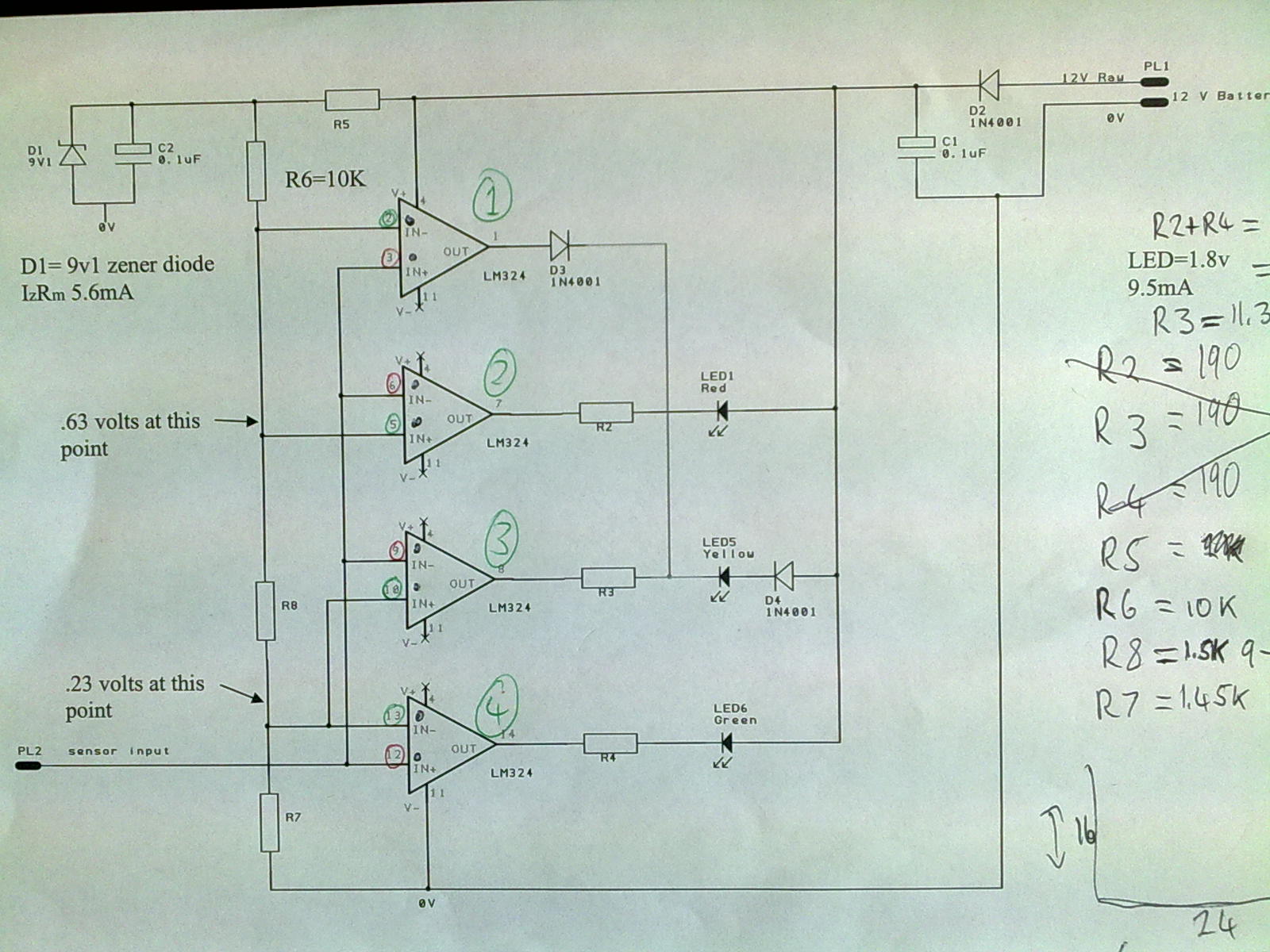
A 12V power supply is connected to the positive terminal, allowing current to flow through a protection diode and a capacitor that smooths the voltage. A zener resistor (R5) limits the current to the zener diode, which regulates the...

The circuit does not guarantee the testing of all defective MOSFETs or all fault conditions in MOSFETs. If the MOSFET is functional, it will operate within the astable multivibrator circuit, resulting in the LED flashing. The described circuit employs an...