
Continuity And Component Tester

The continuity tester is a simple yet effective tool used to check the integrity of electrical connections and circuits. The primary function of this device is to provide an audible indication when a closed circuit is detected, signaling that current can flow between the two probes. The schematic diagram typically includes a power source, such as a battery, a resistor, a diode, and a piezoelectric buzzer or speaker to produce the sound.
In the schematic, the battery serves as the power supply, providing the necessary voltage to the circuit. The probes are connected to the circuit, and when they touch a conductive path, an electric current flows through the circuit. This current passes through a resistor, which limits the current to a safe level for the buzzer.
The diode may be included to protect the circuit from reverse polarity, ensuring that the current only flows in one direction. When the probes are connected, the current activates the piezoelectric buzzer, producing a beep sound that indicates continuity.
The design of the continuity tester is straightforward, making it accessible for both professional and amateur electronics enthusiasts. The components can be easily sourced, and the circuit can be assembled on a breadboard or printed circuit board (PCB) for more permanent applications.
This device is essential in various applications, including troubleshooting electrical systems, verifying connections in wiring, and ensuring that circuit paths are complete before powering up devices. Overall, the continuity tester is a valuable tool in the field of electronics, providing immediate feedback on circuit integrity.This continuity tester gives a beep sound if detect an electric current conduction between its probes. Here is the schematic diagram of this audible.. 🔗 External reference
Related Circuits
The example circuit is designed for an automatic animal feeder. When the animal activates the switch, the PICAXE microcontroller detects this input. The program within the microcontroller then sends an output signal from pin 6, energizing a relay. This...

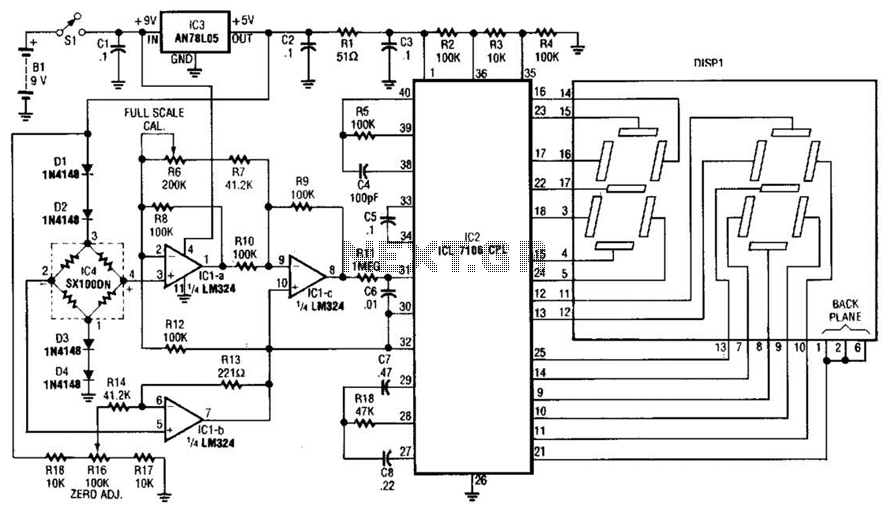
Gates G1 and G2, along with resistors R1 and R2, create a straightforward voltage monitor with a trip point set at 1 volt. Gate G3 functions as an inverter. The display section of the tester features a common anode...

The battery tester utilizes four transistors and two LEDs to indicate the status of any battery being tested. Transistors Q3 and Q4 are configured in a Darlington arrangement, providing extremely high gain. LED L2 illuminates when a small positive...
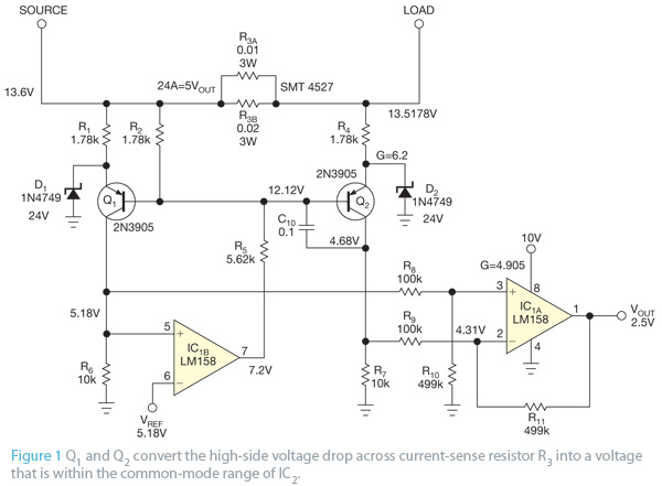
This design concept originated from the lack of access to advanced integrated circuits (ICs) that are capable of sensing current. A discrete circuit was required that could be easily constructed while still maintaining accuracy comparable to that of modern...
This circuit is designed to prevent further damage to old equipment that may be in unknown condition, particularly to devices that are already shorted. The circuit functions as a protective measure for vintage or malfunctioning electronic devices. It is particularly...
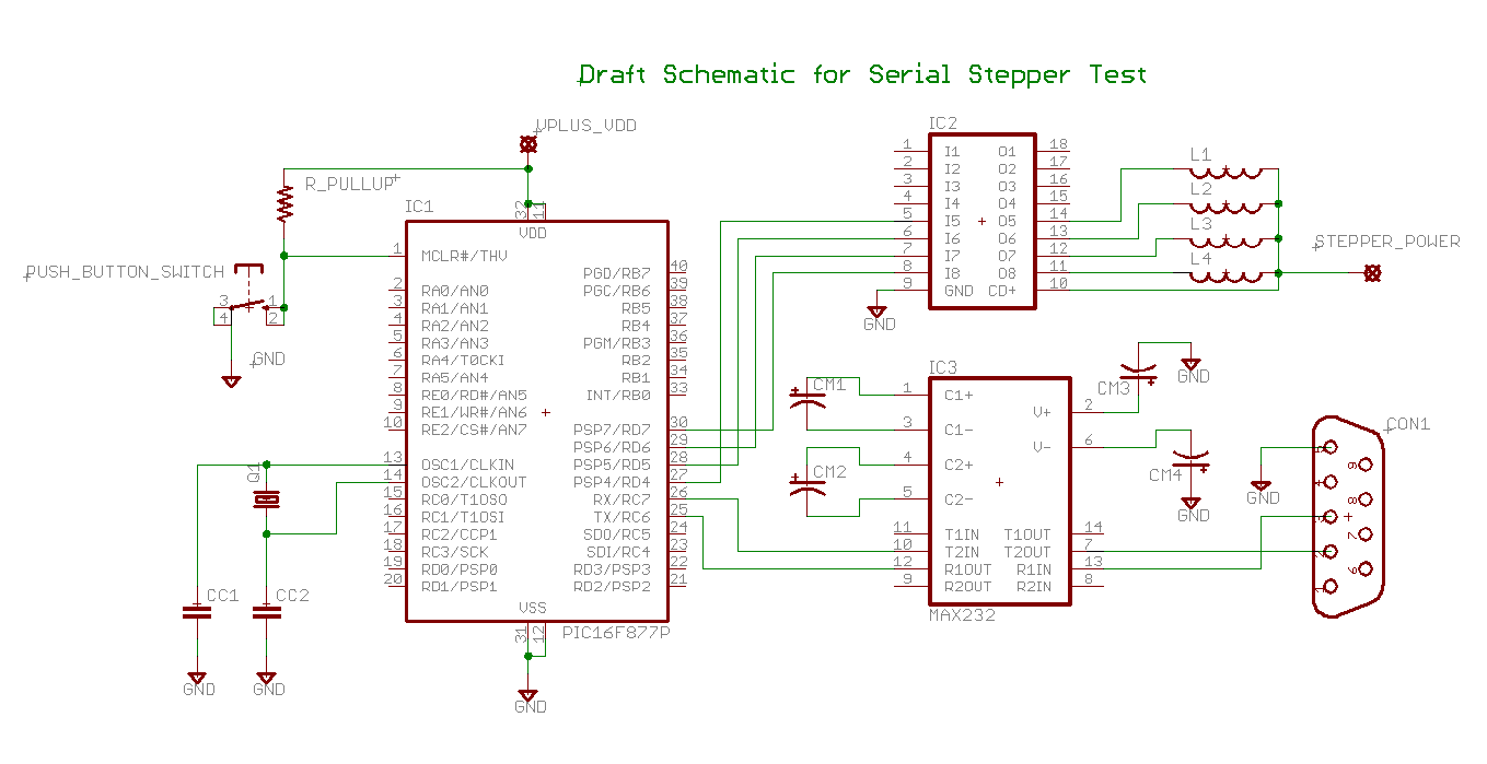
Determining the identification of drive wires on a unipolar stepper motor, which is commonly found in surplus or salvaged equipment. The platform utilized is a PIC16F877A microcontroller programmed with BoostC, interfaced via RS232 to a PC running a terminal...