
12 volt car battery monitor

The circuit employs a series of transistors and light-emitting diodes (LEDs) to provide visual feedback regarding the battery's voltage status. The design utilizes three NPN transistors (Q1, Q2, Q3) configured as switches to control the respective LEDs (D1, D2, D3).
When the battery voltage falls below 11.5V, the base of transistor Q1 receives sufficient voltage, turning it on and allowing current to flow through LED D1, which indicates a low battery condition. This serves as a warning to the user that the battery needs recharging.
As the voltage rises to between 11.5V and 13.5V, the voltage at the base of transistor Q2 also becomes adequate to turn it on, activating LED D2. This state indicates that the battery is in a moderately charged state, which is acceptable for normal operation.
Once the battery voltage exceeds 13.5V, transistor Q3 is activated, allowing current to pass through LED D3. This indicates that the battery is fully charged and operating within a healthy voltage range.
The circuit is powered by a 12V source connected between terminals A and B, which provides the necessary voltage for operation. The design allows for flexibility in the choice of LEDs, enabling the use of different colors for each voltage range, enhancing visual differentiation for the user.
Overall, this battery monitoring circuit provides a simple yet effective method for assessing the state of charge of a car battery, using straightforward components and clear visual indicators.This circuit can be used to monitor the voltage level of a car battery. When the battery voltage is 11. 5V or less the transistor Q1 is on and D1 glowing. When LED battery voltage is between 11. 5 to 13. 5 V, the transistor Q2 is on and the glowing LED D2. When the battery voltage is above 13. 5 V, the transistor Q3 is on and the LED D3 will be brigh t. The 12 volt control can be connected between terminals A and B and for the convenience of using LEDs of different colors. 🔗 External reference
Related Circuits
This battery allows the indicator to the car battery voltage monitor. The indicator has four LEDs which indicate power. The more LEDs, the higher the voltage. The last LED is a flashing LED. It comes on when the accuspaning...
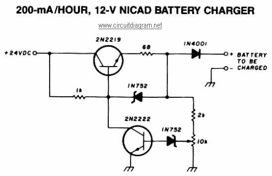
A 12V NiCAD battery charger circuit with a charging rate of 200mA per hour. This circuit initially charges the battery at 75mA until it reaches a full charge, after which the current is reduced to a trickle rate. The...
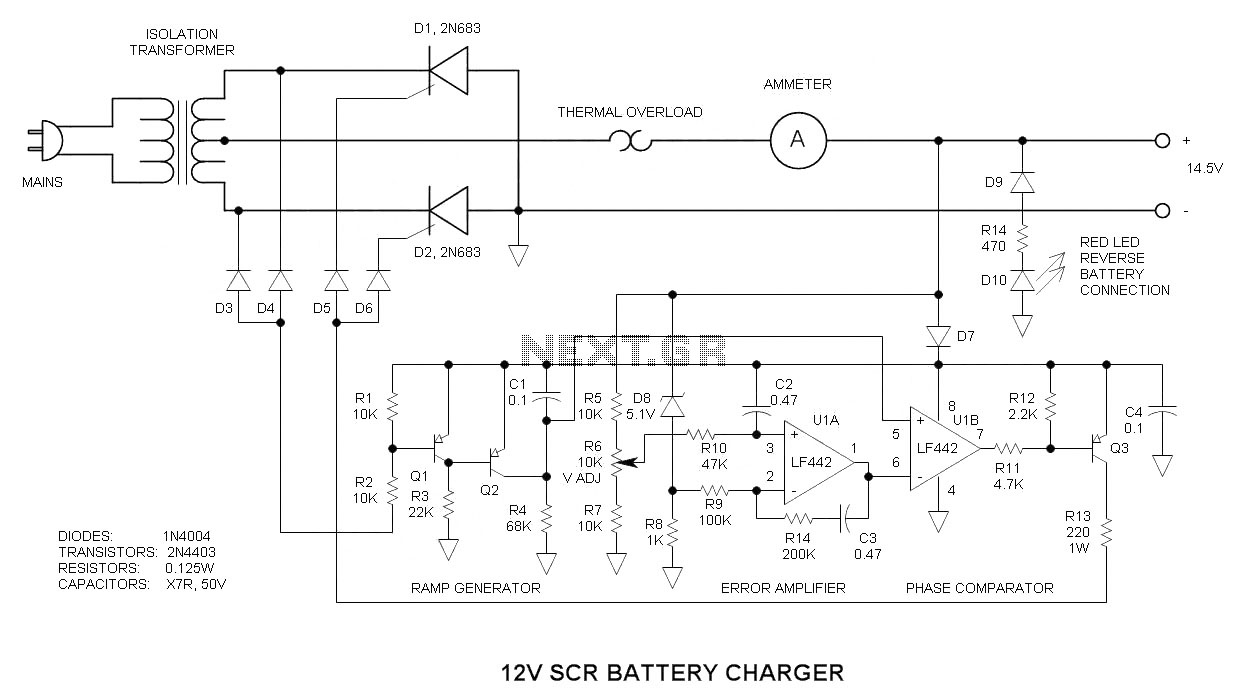
This 12V SCR battery charger circuit is unique in several aspects, which contribute to its complexity. The 12V SCR (Silicon Controlled Rectifier) battery charger circuit is designed to efficiently charge lead-acid batteries while providing a reliable and stable charging process....
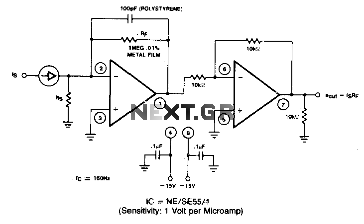
A filter removes the DC component of the rectified AC, which is then scaled to RMS. The output is linear from 40 Hz to 10 kHz or higher. The described circuit primarily consists of a filter designed to eliminate the...
At this voltage regulator prototype the maximum current, with output shortcircuited it was only 0.5 A, so no overheating occurred. In this DC voltage regulator circuit, T1 is for current limitation. As soon as the voltage on the R2...
The block diagram below illustrates the connection of a removable memory card, or MMC card, to its corresponding components. The memory card operates in two signal modes: SD mode and SPI mode. In SD mode, all pins of the...