
12V Battery Charger with SCR

The 12V SCR (Silicon Controlled Rectifier) battery charger circuit is designed to efficiently charge lead-acid batteries while providing a reliable and stable charging process. The circuit typically consists of an SCR, a transformer, diodes, resistors, and capacitors.
The SCR serves as the primary control element in the circuit, allowing current to flow to the battery only when triggered by a gate signal. This feature enables precise control over the charging process, making it suitable for various battery types. The transformer steps down the AC voltage from the mains supply to a lower AC voltage suitable for charging the battery.
Diodes are incorporated to rectify the AC voltage into DC, ensuring that the battery receives the correct polarity and voltage level. Resistors may be used to limit the current flowing into the battery, preventing overcharging and potential damage. Capacitors are included to smooth out the rectified output, providing a more stable voltage to the battery.
The unique aspects of this circuit may include additional features such as automatic cutoff mechanisms, which disconnect the charger once the battery reaches full charge, or the ability to handle varying input voltages. These innovations can complicate the circuit's design and operation, necessitating a thorough understanding of each component's function and interaction within the overall system.
In summary, the 12V SCR battery charger circuit is an advanced design that combines several electronic components to provide a safe and efficient charging solution for batteries, making it a valuable tool for applications requiring reliable battery maintenance.This 12V SCR battery charger circuit differs from the norm in a number of ways, all of which make it difficult to understand 🔗 External reference
Related Circuits
It is difficult to envision modern society without batteries. A quick inventory of gadgets in any household reveals a surprising number of battery-operated devices. Most of these devices utilize penlight batteries, and environmentally conscious users are likely opting for...
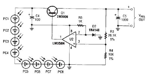
The circuit diagram illustrates a portable solar charger that utilizes an LM358N operational amplifier and a single transistor. This regulator delivers a constant output of 2.4 volts DC, suitable for powering small devices requiring energy from two AA battery...
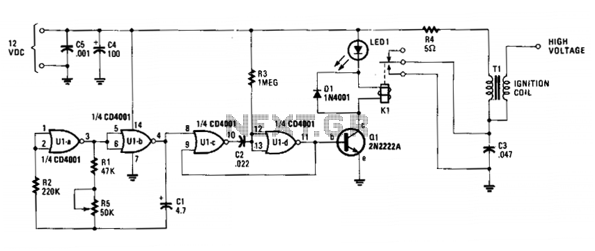
The circuit is fundamentally an auto ignition coil paired with a set of points that perform a similar function. It employs a pulsing circuit constructed from a single CMOS NOR integrated circuit (U1) to open and close relay contacts,...
To charge lead-acid batteries, a circuit can be utilized that consists of a current-limited power supply and a flyback converter topology. The circuit designed for charging lead-acid batteries incorporates a current-limited power supply alongside a flyback converter topology to...

The circuit is simple to assemble and install, and it notifies the user when the battery voltage drops below a predefined threshold set by R1, which is a 10,000-ohm potentiometer. It can signal through LED1 that the battery may...
The rechargeable Li-ion battery charger circuit operates with a limited current charging and constant voltage. The charging current flows from the rectified voltage of the transformer through the transistor T1, diode D5, resistor R2, and back to the battery....