
Clock Circuit Design

The circuit design involves a high voltage supply that requires careful consideration to ensure safety and functionality. An isolation transformer is essential for protecting the circuit during testing and troubleshooting. The choice of a 1:1 transformer rated at 30VA is appropriate, as it effectively isolates the circuit ground from the AC mains ground, which is critical for preventing electrical hazards.
In terms of the Nixie tube configuration, the common anode design necessitates that the high voltage side aligns with this configuration. A reversed polarity could lead to malfunctioning of the display, as the Nixie tubes may not light up correctly if they are driven as common cathode. This design flaw must be addressed to ensure proper operation.
The counting logic implemented in the circuit must be meticulously reviewed, particularly the carry/reset mechanism for the tens digit of seconds and minutes. The current logic fails to account for the correct transition at the count of 5, which will prevent the display from showing the expected values. This oversight can lead to incorrect timekeeping, necessitating a redesign of the counting logic to ensure that the counters operate as intended.
Diodes should be incorporated to prevent the time set buttons from inadvertently affecting adjacent counters. This will help maintain the integrity of the counting function during adjustments. Prototyping the circuit on a breadboard is highly recommended to validate the design before committing to a printed circuit board (PCB). This step allows for testing the carry/reset logic and verifying that the counters function correctly with visual feedback from LEDs.
Furthermore, the use of resistors between the CMOS logic and the transistors is crucial. These resistors limit the current flowing into the transistor base, which protects the IC from excessive current draw and prevents false triggering due to leakage currents. The reliability of the circuit can be significantly improved by adhering to these design principles.
In conclusion, careful attention to the polarity of the Nixie tube connections, the counting logic, the integration of diodes for button functionality, and the use of resistors for current limiting will enhance the overall performance and safety of the high voltage supply circuit. Proper validation through prototyping will ensure that the design meets the intended specifications before final implementation.Your HVsupply will work, but for your own safety and to avoid accidental damage to your circuit if the event you need to troubleshoot with a scope, I strongly encourage the use of an isolation transformer on the 120VAC input. Just a little 1:1 transformer, 30VA is plenty. That`ll get your circuit ground isolated from AC Mains ground, saving you much potential misery later.
2) Polarity of HV / connection of transistors: unless I`ve totally lost my mind, I do nelieve your polarity is reversed. Nixies are common anode (positive common) and your whole HV side is designed as though they were common cathode (common negative). Since I have not yet looked up those CMOS part numbers and analyzed your logic, I`m not yet sure what Item (2) above is going to do to the logic design, e.
g. will a second `stage` of transistors (or some inverter ICs) become necessary. As for the counting logic, I`m not willing to spend any more time on that until I see if you come back and post a response. No offense, but you are brand new here, lots of new people post once and never come back, and I don`t want to find out I`ve wasted my time.
What I notice immediately about your counters is how you do your Carry/Reset. You need to re-evaluate how you are doing that on the ten`s digit of seconds and minutes because the way you have it now you will never see a "5" in those positions. Your hours look like they will count to 19 or 29 before resetting, probably not what you intended. Also your Time Set buttons are going to have unintended effect of resetting the counter "to the right" of the counter you`re trying to set.
Diodes are needed. Edit to add: I would definitely assemble and debug that string of CD4017s on a breadboard before committing it to a PCB. As above, I find your Carry/Reset scheme dodgy and would want to prove out the design - using LEDs as needed to observe counter states - before going forward with it.
I`ve gotten 1:1 transformers for my projects from Mouser and/or Digikey. "Isolation Transformer" is a good search keyword to locate them. I don`t know much about Norway: are your AC mains 120V Or are you already stepping down from 250 to 120 and just not showing it on the drawing I ask because a small 250 to 120 (2:1) is much easier to get than a 1:1. Most any "world power adapter kit" includes a 2:1 transformer. The resistors between the CMOS and the transistors limit current. Without them far more base current is "pulled" out of the IC than is really necessary. Also without resistors any little bit of off-state leakage current from the IC will falsely turn on the transistors.
I assure you the resistors will not prevent the transistors from turning on properly. I`ve designed and built several Nixie devices using MPSA42 driven from CMOS through 33K resistors and they work just fine. Meanwhile. look at your counters again. I`m pretty sure that when you Carry & Reset (on the 10 sec and 10 min digits) you should be doing it when count hits 6, not 5.
After all, on the 1 sec and 1 min digits you are carrying on 10 (next clock pulse after 9) not 9. 🔗 External reference
Related Circuits
This circuit is designed to detect incoming calls on a cellular phone, even when the phone's ringer is turned off, by utilizing a flashing LED. The device should be positioned a few centimeters away from the cellular phone, allowing...
This project is suitable for individuals who enjoy experimenting with electronics. It presents a low risk of damaging the unit. This project involves creating a simple electronic circuit that allows users to engage in hands-on experimentation without significant risk. The...
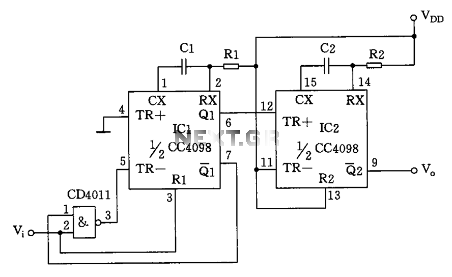
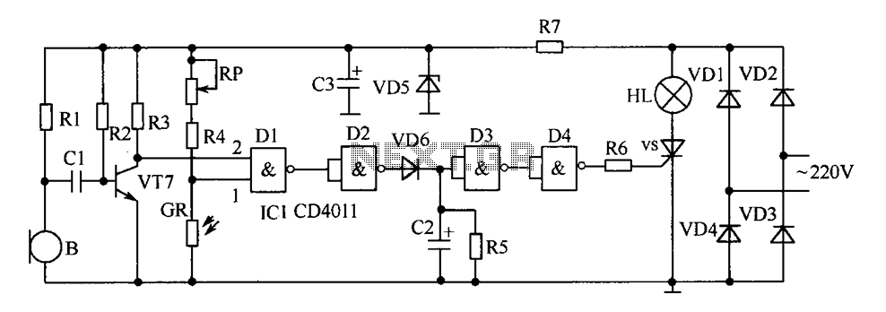
The circuit depicted features a double oscillator utilizing a monostable multivibrator CC4098 and a quad 2-input NAND gate CC4011, among other components. This circuit allows for adjustable frequency and duty cycle. It is primarily designed as a keying oscillator,...
There are numerous circuits designed for low voltage regulators. However, for higher voltages, such as those required for valve circuits, the approach differs. This is the reason for the design of a simple regulator capable of handling these voltages....
This sawtooth generator circuit utilizes a 741 operational amplifier (op-amp) and functions as a musical sound synthesizer. The sawtooth input signal is continuously modified through potentiometer P2 to create varying waveforms. The sawtooth generator circuit primarily employs the 741 op-amp...
The delay-saving lamp circuit functions as a sound and light control delay energy-saving lighting system. It can directly replace a standard light switch without modifying the existing lighting circuits. In bright or daytime conditions, the sound control feature ensures...