12V 40Watts (2x20Watts) Fluorescent Tube Lamp Inverter

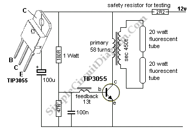
A 40-watt fluorescent tube lamp or two 20-watt tubes in series will be driven by this circuit. The transformer is wound on a ferrite rod with a diameter of 10 mm and a length of 8 cm.
The circuit described is designed to operate a 40-watt fluorescent tube lamp or two 20-watt fluorescent tubes connected in series. This arrangement is particularly useful in applications where space is limited, and the need for efficient lighting is paramount. The transformer utilized in this circuit is constructed on a ferrite rod, which serves as the core material. The choice of ferrite is significant due to its high magnetic permeability, which enhances the efficiency of the transformer while minimizing losses.
The transformer is wound on a ferrite rod with a diameter of 10 mm and a length of 8 cm. The dimensions of the ferrite core are critical in determining the inductance and the overall performance of the transformer. The winding configuration should be optimized to ensure that the transformer can handle the required power without saturating, which would lead to inefficiencies and potential damage.
In operation, the circuit provides the necessary starting voltage and current to ignite the fluorescent tubes. Fluorescent lamps require a higher initial voltage to start the discharge process, which is typically achieved through a ballast circuit. The transformer in this design acts as a ballast, regulating the current flowing through the tubes once they are lit, thereby ensuring stable operation.
The circuit may also include additional components such as capacitors for power factor correction and diodes for rectification purposes, depending on the specific requirements of the application. Proper attention to component ratings and circuit design will ensure reliability and longevity in the operation of the fluorescent lighting system.
Overall, this circuit is a practical solution for driving fluorescent lamps, offering an efficient means of lighting that can be adapted for various applications, including residential, commercial, and industrial environments.A 40 watt fluorescent (tube lamp, TL) or two 20-watt tubes in series will be driven by this circuit. The transformer is wound on a ferrite rod 10mm dia and 8cm.. 🔗 External reference


