Subwoofer Filter Circuit Using Op-Amp TL072
The subwoofer filter circuit is designed to enhance the audio experience in automotive environments by ensuring that low-frequency signals are accurately passed to the subwoofer, while higher frequencies are attenuated. The use of the TL072 op-amp is advantageous due to its low noise and high-speed operation, making it suitable for audio applications.
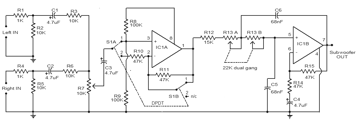
The configuration of the circuit begins with the audio signal input, which is fed into the DPDT switch S1. This switch allows the user to select between two different phase options for the subwoofer, ensuring that the sound waves from the subwoofer and the main speakers are coherent, thus enhancing sound quality. The buffer stage provided by IC1A isolates the input signal from the subsequent filtering stage, preventing loading effects that could distort the audio signal.
The low-pass filter functionality is achieved through IC1B, which is configured to allow frequencies below a predetermined cutoff frequency to pass while attenuating frequencies above this threshold. The cutoff frequency is determined by the values of the components used, particularly the dual-gang potentiometer R13, which allows for fine-tuning of the filter's response. This adjustability is crucial for optimizing the performance of the subwoofer in different acoustic environments.
Additionally, the level control potentiometer R7 provides the ability to adjust the output level of the filtered audio signal, allowing for integration with other audio components in the system without distortion or clipping. The overall design of this subwoofer filter circuit is aimed at achieving high fidelity and clarity in low-frequency sound reproduction, making it an essential component for automotive audio systems.Here is a simple subwoofer filter circuit that can be powered by a 12V DC. This circuit is very useful in automotive applications subwoofer. The circuit is a low pass filter whose pass frequency can be set between 60 to 160 Hz The circuit is built around the TL072 dual op amp IC BIFET. Of the two operational amplifiers inside the chip, IC1A is wir ed as a buffer. The left and right audio inputs after mixing is fed to the input of the IC1A using the DPDT switch S1. Switch S1 is the phase control switch which can be used to make the subwoofer in phase with other speakers.
When S1 is in position 2, 180 degree phase shift will be induced. POT R7 can be used for controlling the level. IC1B forms the low pass filter whose pass frequency can be controlled by adjusting the dual gang POT R13.
Related Circuits
 Schematic Diagram Electronic FM Telephone Transmitter Circuit
Electronic FM Telephone Transmitter SchematicThe following schematics design pictures is a circuit diagram FM telephone transmitter that built on a PC board layout which is so small it can simply be fitted within the housing of a telephone creating it an instant pseudo-speak earphone. This circuit diagram FM telephone transmitter...
 Series Inductor Filter
In this arrange ment a high value inductor or choke L is connected in series with the rectifier element and the load, as illustrated in figure. The filtering action of an inductor filter de pends upon its property of opposing any change in the current flowing through it. When the...
 Vocal Stripper Circuit
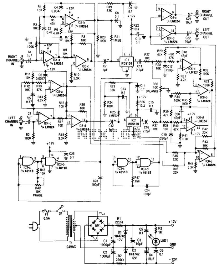
Right- and left-channel signals pass through 1 C4-a and -b buffer amps into active crossover IG5; low frequencies are sent to the IC6-c mixer, and middle and high frequencies are sent to the analog delay lines of 1C1 and 1C2. That output passes through lC6-a and -d to filter...
 Circuit examples
Input J4 has offset function provided that no plug is inserted into J4 as the switching contact of J4 is connected to the positive supply voltage in this case (via the protection resistor R8). At J5 the inverting sum of all inputs is available. J6 outputs the non-inverting sum. P5...
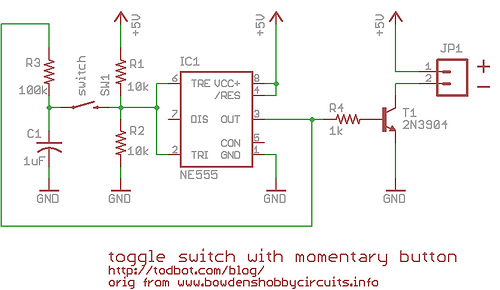 momentary button as onoff toggle using 555
Most all work off of some flip-flop like principle. And while I could have suggested a true flip-flop chip, I thought it would be cooler if you could use a 555 timer chip (which contains a single flip-flop and a couple of comparators). After scouring my childhood collection of