
Car battery monitor III

The circuit utilizes a basic voltage monitoring system that incorporates a 10,000-ohm potentiometer (R1) to establish the desired voltage threshold. When the battery voltage is above this threshold, the circuit remains inactive. However, if the voltage decreases below this level, the circuit activates LED1, providing a visual indication of a potential issue with the battery.
The 2N3904 transistor can be employed as a switching device in this configuration. When the voltage at the base of the transistor, controlled by the voltage divider formed by R1 and a reference resistor, falls below the set limit, the transistor turns on, allowing current to flow through LED1. This action illuminates the LED, alerting the user to the low battery condition.
In terms of assembly, the circuit requires minimal components: the potentiometer for voltage setting, the 2N3904 transistor, a current-limiting resistor for the LED, and the LED itself. The connections should be made carefully to ensure that the transistor is correctly oriented and that the LED is connected with the proper polarity to function effectively.
This circuit can be used in various applications where battery monitoring is essential, providing a straightforward and effective solution for ensuring battery health and reliability.The circuit is quick and easy to put together and install, and tells you when battery voltage falls below the set limit as established by Rl (a 10,000-ohm potentiometer). It can indicate, via LED 1, that the battery may be defective or in need of change if operating the starter causes the battery voltage to drop belciw the present limit.
You can use the 2N3904 or any equivalent.
Related Circuits
With the advent of modern integrated circuits (ICs), sophisticated circuits today are no longer required to be complex and lengthy. The chips themselves contain most of the intricate circuitry built-in and can independently perform the desired functions. For instance,...
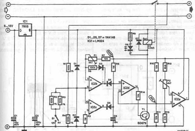
A simple battery charger is designed to disconnect the battery when the charge voltage reaches its nominal level and reconnect when the battery voltage drops below a predefined threshold. This is achieved using a circuit diagram that incorporates a...
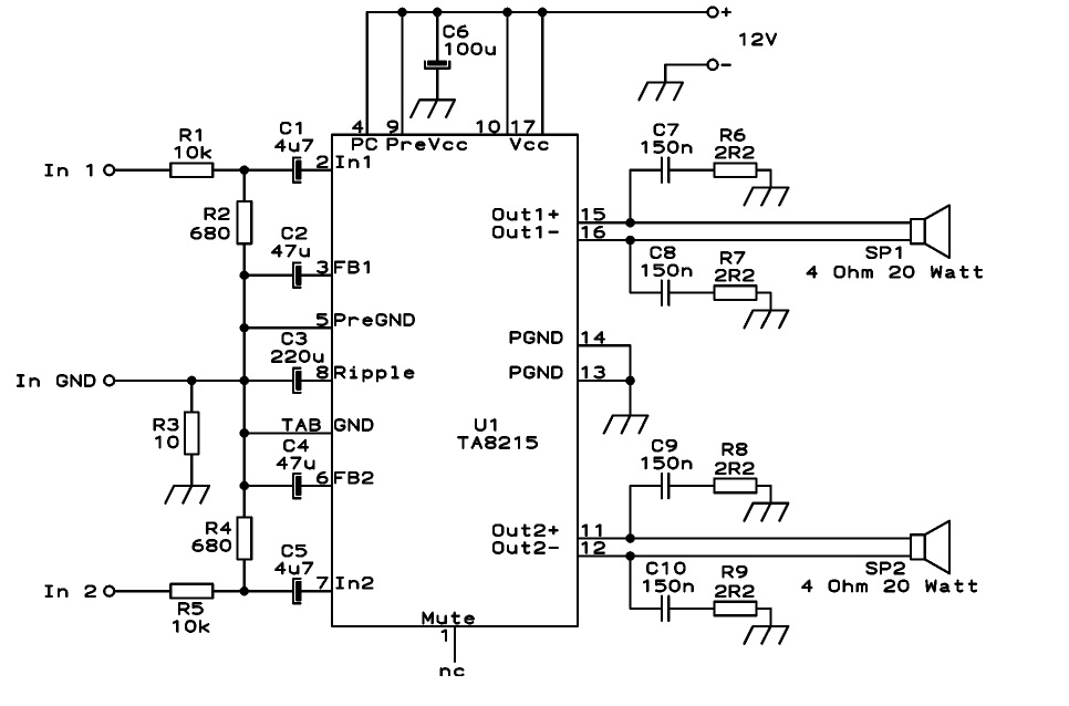
This circuit is designed as a stereo BTL (Bridge-Tied Load) 15W audio power amplifier using the TA8215 integrated circuit developed by Toshiba. Two TA8215 ICs are utilized in this configuration to achieve four output channels, with each IC providing...
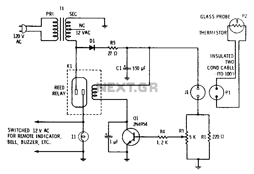
A filtered 15 V DC supply is applied to a series circuit that includes a thermistor (R2) and a parallel combination of resistors (R1 and R3). The transistor (Q1) functions as a switch, with its state controlled by the...
Observing and addressing the phase adjustment issues in electric transmission lines manually poses significant challenges, particularly in recording and normalizing three major problems. This design encompasses both software and hardware components, developed over an extended period. It is intended...
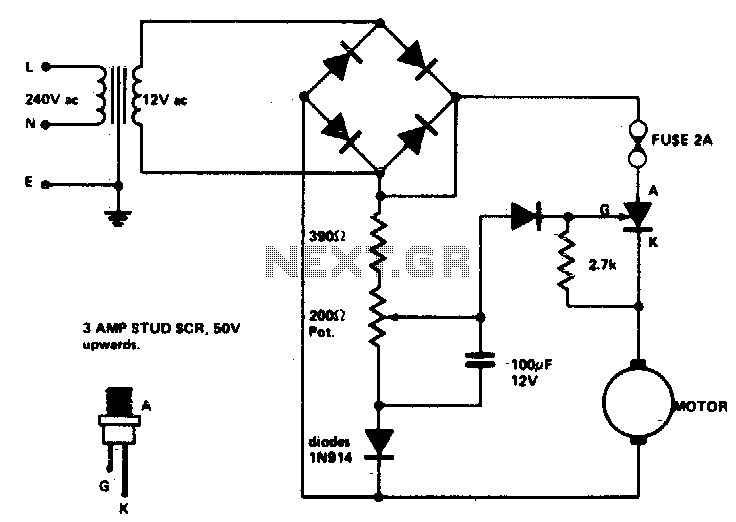
Low voltage speed control provides excellent starting torque and effective speed regulation. Additionally, a reversing switch can be integrated into the motor leads. Low voltage speed control circuits are essential in applications where precise motor control is required, such as...