
12V Battery Meter with 4 LEDs

The circuit utilizes the LM339 quad voltage comparator to create a visual representation of the battery's charge status through a series of light-emitting diodes (LEDs). Each comparator within the LM339 operates by comparing the voltage at its non-inverting input (+) against the voltage at its inverting input (-). In this configuration, a stable 5V reference voltage is applied to the non-inverting inputs of all four comparators. The inverting inputs are connected to various points along a voltage divider that scales the battery voltage down to a level suitable for comparison.
The voltage divider is typically composed of two resistors in series, where the junction between the resistors connects to the inverting input of the first comparator. The subsequent comparators are connected to further points along the divider, allowing them to detect progressively lower voltage thresholds. The thresholds are set in such a way that each comparator corresponds to a specific battery voltage level: for instance, the first comparator might activate at 12.7V, the second at 12.4V, the third at 12.1V, and the fourth at 11.7V.
The LEDs are connected in parallel with the output of each comparator. When the voltage at the inverting input exceeds the 5V reference, the output of the comparator goes low, allowing current to flow through the LED, thus illuminating it. This provides an immediate visual indication of the battery's charge status. The calibration of the circuit is critical and is performed using a 2K potentiometer. By adjusting this potentiometer, the user can ensure that all LEDs illuminate when the battery voltage is at full charge (12.7 volts), and no LEDs light up at the dead battery threshold (11.7 volts).
It is important to note that variations in battery chemistry, such as wet cell or gel cell, as well as temperature fluctuations, can affect the exact voltage levels at which the LEDs activate. Therefore, the circuit may require periodic recalibration to maintain accuracy across different operating conditions. Each LED represents a 25% increment in charge condition, translating to approximately 300 millivolts per LED. Thus, the illumination of three LEDs indicates a charge level of around 75%, two LEDs indicate 50%, and so forth, providing a clear and intuitive display of the battery's health.In the circuit below, a quad voltage comparator (LM339) is used as a simple bar graph meter to indicate the charge condition of a 12 volt, lead acid battery. A 5 volt reference voltage is connected to each of the (+) inputs of the four comparators and the (-) inputs are connected to successive points along a voltage divider.
The LEDs will illuminate when the voltage at the negative (-) input exceeds the reference voltage. Calibration can be done by adjusting the 2K potentiometer so that all four LEDs illuminate when the battery voltage is 12.7 volts, indicating full charge with no load on the battery. At 11.7 volts, the LEDs should be off indicating a dead battery. Each LED represents an approximate 25% change in charge condition or 300 millivolts, so that 3 LEDs indicate 75%, 2 LEDs indicate 50%, etc. The actual voltages will depend on temperature conditions and battery type, wet cell, gel cell etc. 🔗 External reference
Related Circuits
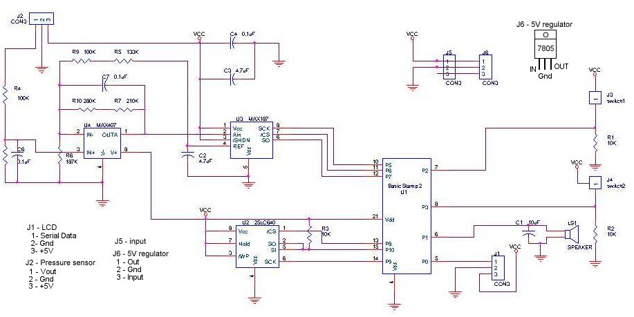
A method for determining altitude involves the use of barometric pressure; however, it presents certain challenges. The relationship between pressure and altitude is not linear but rather complex, a concept developed by the army in the 1930s. The equation...
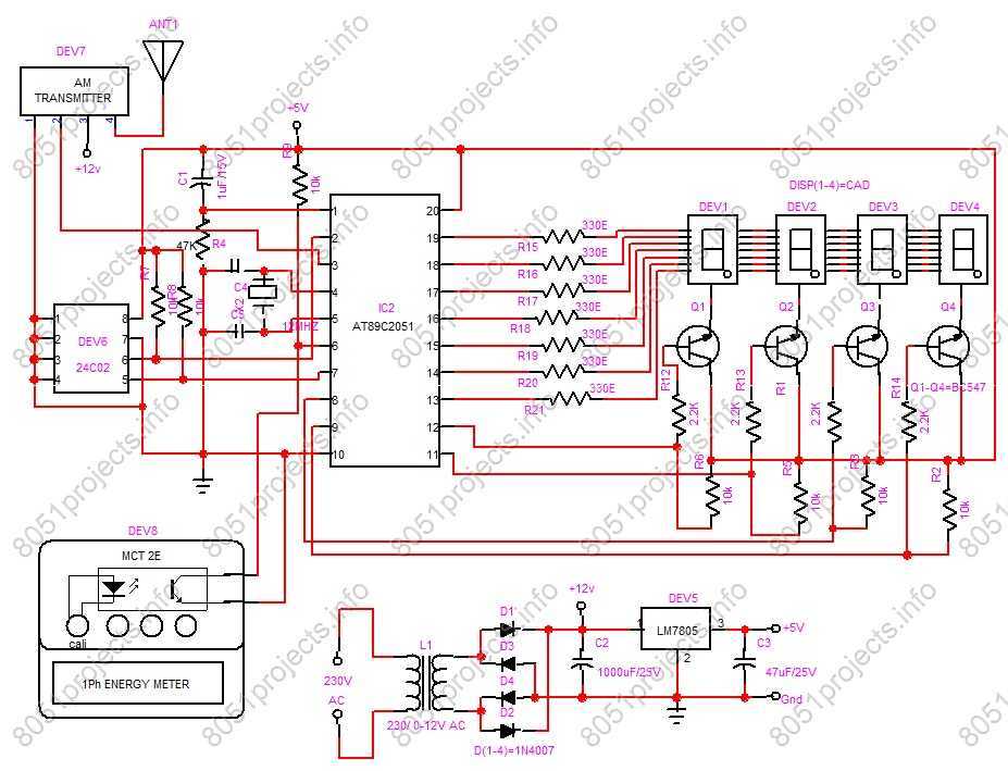
RF based Automatic meter reading, or AMR, is the technology of automatically collecting data from energy meter and transferring that data to a central database for billing and/or analyzing. This means that billing can be based on actual consumption...
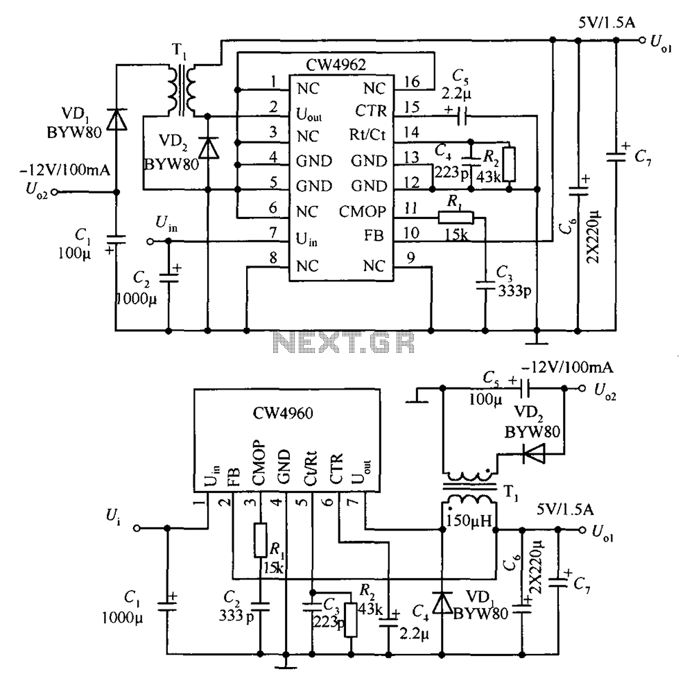
The circuit described is a stabilized power supply utilizing the CW4962 and CW4960 components, providing +5V at 1.5A and -12V at 100mA. The +5V output serves as the main power supply. The output circuit employs a transformer rather than...
The DS2715 is a comprehensive NiMH (Nickel Metal Hydride) smart charger solution featuring load detection, making it ideal for cost-effective applications. The DS2715 smart charger integrates several key functionalities designed to enhance the charging process for NiMH batteries. It employs...
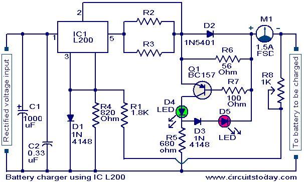
A simple battery charger circuit with reverse polarity indication is presented here. The circuit utilizes the L200 integrated circuit (IC), which is a five-pin variable voltage regulator. The charging circuit can be powered by DC voltage from either a...
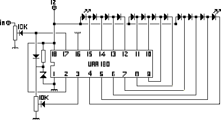
The NL3ASD schematic pages provide the schematics for a LED VU meter utilizing the UAA180 integrated circuit. The NL3ASD schematic pages feature a comprehensive design for a LED VU meter that employs the UAA180 IC, known for its audio signal...