
12V Electronic Thermostat with Relay

This thermostat circuit is designed for controlling a relay that powers a small space heater, ensuring safe and efficient operation. The core of this circuit utilizes a thermistor, which is a temperature-sensitive resistor, and a potentiometer to create a voltage divider that varies with temperature changes. The LM339 voltage comparator is employed to compare the voltage from this divider against a reference voltage, allowing it to determine when to activate or deactivate the relay.
The thermistor is specified at 1.7K ohms at 70°F, providing a suitable sensitivity for detecting temperature changes. The 5K potentiometer allows for fine-tuning of the circuit to establish the desired temperature threshold. The output from the thermistor and potentiometer combination generates approximately 50 millivolts for each degree Fahrenheit of temperature change, which is critical for the LM339’s operation.
The reference voltage for the LM339 is set using two 1K resistors, which provide a stable half-supply voltage. This configuration assists in establishing a hysteresis range of approximately 3 degrees Fahrenheit, ensuring that the relay does not rapidly toggle on and off due to minor fluctuations in temperature. The hysteresis can be adjusted via a 10K resistor connected between pins 1 and 7 of the LM339, allowing for customization based on specific application needs.
In typical operation, the series resistor is adjusted so that the relay disengages at the desired temperature. A subsequent drop of three degrees will re-engage the relay, allowing the heater to operate until the temperature rises back to the preset level. Notably, the relay action can be reversed by switching the positions of the thermistor and potentiometer, enabling the circuit to turn off the heater when the temperature drops below a certain threshold.
The inclusion of a 5.1-volt zener diode ensures voltage regulation within the circuit, protecting it from variations in the 12-volt supply. This regulation is essential for maintaining consistent operation, particularly in environments where power supply fluctuations may occur. The voltage across the thermistor is monitored to maintain it at approximately half the supply voltage (around 2.6 volts) within the defined temperature range.
Overall, this thermostat circuit is versatile, allowing for the use of various thermistors as long as their resistance is above 1K ohm at the target temperature. The design considerations for selecting the series resistor emphasize that it should be approximately twice the resistance of the thermistor to facilitate optimal adjustment of the control mechanism.Here is a simple thermostat circuit that can be used to control a relay and supply power to a small space heater through the relay contacts. The relay contacts should be rated above the current requirements for the heater. Temperature changes are detected by a (1.7K @ 70F) thermistor placed in series with a 5K potentiometer which produces about 50 millivolts per degree F at the input of the LM339 voltage comparator.
The two 1K resistors connected to pin 7 set the reference voltage at half the supply voltage and the hysteresis range to about 3 degrees or 150 millivolts. The hysteresis range (temperature range where the relay engages and disengages) can be adjusted with the 10K resistor between pins 1 and 7.
A higher value will narrow the range In operation, the series resistor is adjusted so that the relay just toggles off at the desired temperature. A three degree drop in temperature should cause the relay to toggle back on and remain on until the temperature again rises to the preset level.
The relay action can be reversed so it toggles off at the lower end of the range by reversing the locations of the 5K potentiometer and thermistor. The 5.1 volt zener diode regulates the circuit voltage so that small changes in the 12 volt supply will not effect operation.
The voltage across the thermistor should be half the supply or about 2.6 volts when the temperature is within the 3 degree range set by the potentiometer. Most any thermistor can be used, but the resistance should be above 1K ohm at the temperature of interest.
The series resistor selected should be about twice the resistance of the thermistor so the adjustment ends up near the center of the control. 🔗 External reference
Related Circuits
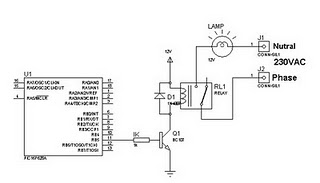
A relay can be controlled using a PIC microcontroller. The circuit illustrates how to control a single relay with the PIC 16F628. When the RB5 port of the PIC is set to high, the relay will activate. This circuit...

A circuit breaker is an automatically operated electrical switch designed to protect an electrical circuit from damage caused by overload or short circuit. Its basic function is to detect a fault condition and, by interrupting continuity, immediately discontinue electrical...
This is a metronome circuit that produces a mechanical sound characteristic. A metronome with a mechanical sound character enhances the enjoyment of musical practice and performance. The metronome circuit is designed to generate a rhythmic sound that aids musicians in...
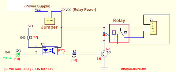
Control a relay from an Arduino-compatible board. When attempting to activate the relay from the Arduino, it takes at least a second to close, and sometimes it does not close at all. Digital pin 2 of the Arduino is...
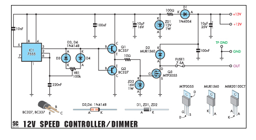
This circuit can function as a speed controller for a 12V motor with a continuous rating of up to 5A or as a dimmer for a 12V halogen or standard incandescent light. The circuit utilizes a pulse-width modulation (PWM) technique...
A simple circuit with which we have the possibility of opening and closing the RL1 contacts. It becomes active by touching a small metal surface. The status of RL1 is indicated by the LED D3. The supply voltage for...