
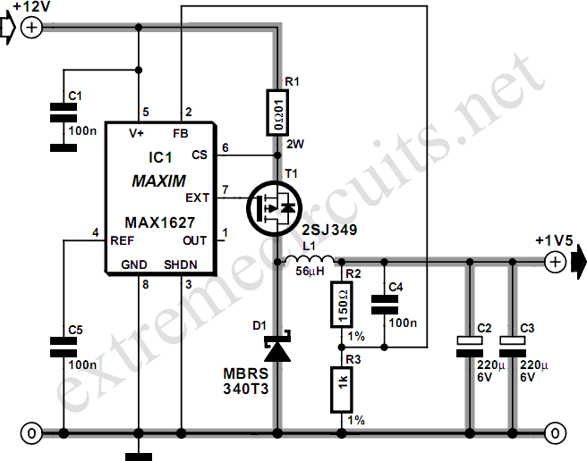
12V Speed Controller/Dimmer

The circuit utilizes a pulse-width modulation (PWM) technique to regulate the speed of the motor or the brightness of the light. It typically consists of a microcontroller or a dedicated PWM controller IC, a power transistor or MOSFET to handle the load, and passive components such as resistors and capacitors for filtering and stability.
For the motor speed control application, the circuit adjusts the duty cycle of the PWM signal, which effectively controls the average voltage supplied to the motor. This allows for smooth acceleration and deceleration, enhancing the motor's performance while minimizing heat generation. The circuit may include additional features such as overcurrent protection to safeguard the motor from excessive current draw.
In the dimmer application, the PWM signal modulates the power delivered to the light source, allowing for a range of brightness levels. This method is more efficient than traditional resistive dimmers, as it reduces wasted energy and heat, making it suitable for long-term use.
The circuit should be designed with adequate heat sinking for the power transistor or MOSFET, especially when operating at higher currents. Proper selection of components, including the PWM frequency, will ensure optimal performance for both motor control and dimming applications.This handy circuit can be used as a speed controller for a 12V motor rated up to 5A (continuous) or as a dimmer for a 12V halogen or standard incandescent.. 🔗 External reference
Related Circuits
Many times we needed a variety of voltages, from a battery 12V. With the circuit, we can take voltages smaller or bigger, positive or negative, from a battery 12V. The idea is based in oscillator roughly 7KHZ, round the...
Most small internal combustion engines commonly used in model building utilize glow plugs for starting. However, glow plugs operate at a voltage of 1.5 V, while components such as fuel pumps, starter motors, and chargers typically operate at 12...
This inverter circuit can provide up to 800mA of 12V power from a 6V supply. For example, you could run 12V car accessories in a 6V (British?) car. The circuit is simple, about 75% efficient and quite useful. By...
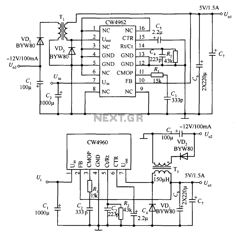
The circuit described is a stabilized power supply utilizing the CW4962 and CW4960 components, providing +5V at 1.5A and -12V at 100mA. The +5V output serves as the main power supply. The output circuit employs a transformer rather than...
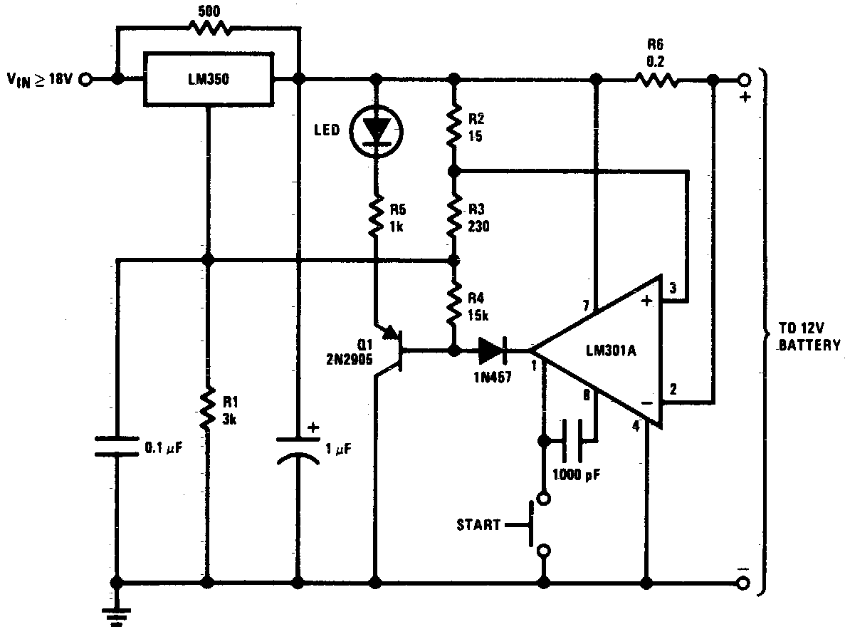
DC 12V Battery Charger Circuit Diagram. This circuit is a high-performance charger for gelled electrolyte lead-acid batteries. The DC 12V battery charger circuit is designed to efficiently charge gelled electrolyte lead-acid batteries, which are commonly used in various applications due...
Pulse width modulation, commonly referred to as PWM, is utilized to regulate the power supplied to a load without sacrificing efficiency. This technique is often employed in controlling the speed of an electric motor. PWM operates by varying the width...