
12v iPad Charger

The proposed charging circuit is designed to efficiently convert a 12V input from a photovoltaic power source down to a stable 5V output, necessary for charging USB devices such as iPads. The Texas Instruments PTN78020 switching regulator is chosen for its high efficiency and ability to handle up to 6A of output current, ensuring that the circuit can meet the power demands of multiple devices simultaneously.
In this circuit, the input voltage is connected to the PTN78020, which regulates the voltage to 5V. The output is then routed to the USB charging port. To address the specific requirements of the iPad, which necessitates a control signal on the data pins for proper charging, voltage dividers are implemented. These dividers are configured to provide the necessary control voltages on the data lines, ensuring compatibility with the iPad's charging protocol.
The circuit schematic should clearly indicate the connections between the input power source, the PTN78020 regulator, and the output USB port, along with the voltage divider network. Proper attention must be given to the component values in the voltage divider to ensure that the correct voltages are achieved without exceeding the maximum ratings of the data pins.
This innovative approach not only mitigates the cost associated with purchasing proprietary chargers but also enhances the utilization of renewable energy resources, contributing to a more sustainable charging solution for electronic devices.Following the 4th Apple iPad charger failing and not wanting to spent even more money with Apple to replace them we decided to try to make 12v powered chargers to make use of the excess PV power we now have during the daytime to charge the iPads and other devices which charge via USB. I have a couple of ready made USB car chargers but these will n ot charge the iPad due to the iPad needing a control voltage on both of the data pins which most commercial 12V chargers don`t seem to supply. The circuit schematic (click for PDF) shows the new charging circuit diagram which uses a Texas Instruments PTN78020 6-A, Wide-input adjustable switching regulator to bring the input voltage down to 5V and then voltage dividers to supply the data lines with the correct voltage.
[more] 🔗 External reference
Related Circuits
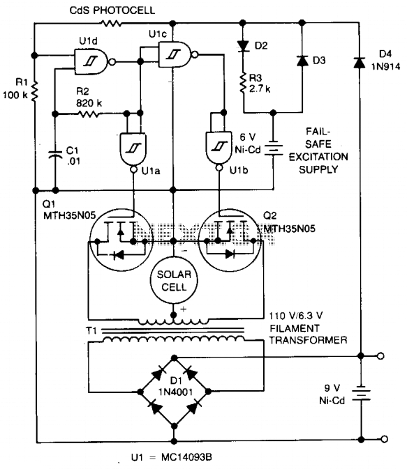
The circuit charges a 9-V battery at approximately 30 mA per input ampere at 0.4 V. U1, a quad Schmitt trigger, operates as an astable multivibrator to drive push-pull MOSFET devices Q1 and Q2. Power for U1 is derived...
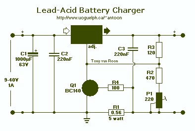
The above pictured schematic diagram is just a standard constant current model with a added current limiter, consisting of Q1, R1, and R4. The moment too much current is flowing biases Q1 and drops the output voltage. The output...
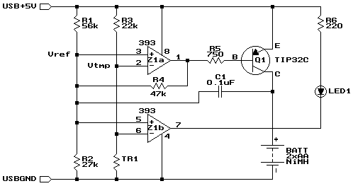
Widely available AA NiMH battery chargers are on the market, including those packaged to charge various battery types such as NiCd and NiCad. This project features a battery charger designed for two AA NiMH or NiCd cells of any...
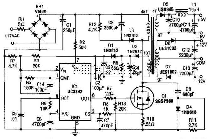
This power supply utilizes an SGS-Thomson UC3842 integrated circuit in an off-line flyback regulator configuration, delivering +5 V at 4 A and ±12 V at 300 mA. This design allows for the use of a compact high-frequency (50 kHz)...

12V NiCad battery charger with a 200mA/h power supply. Refer to the specified page for an explanation regarding the related circuit diagram. The circuit for a 12V NiCad battery charger designed to supply a current of 200mA/h typically includes several...
The accumulator charger circuit must provide a voltage that matches the specifications of the batteries being charged. For a 12-volt accumulator, the output voltage should not exceed 12 volts, nor should it fall significantly below this threshold. Failure to...