
Lead Acid Battery Charger II

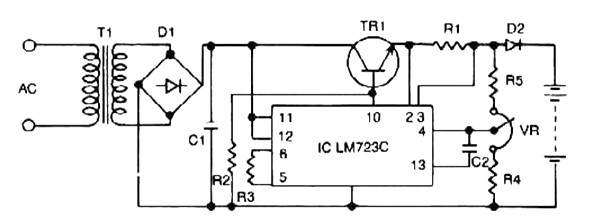
The described circuit operates as a constant current source with an integrated current limiting feature, utilizing a transistor (Q1), resistors (R1, R2, R3, R4), and a potentiometer (P1). The primary function of this circuit is to provide a stable output current while preventing excessive current flow that could potentially damage connected components. The transistor Q1, which can be a BC140 or its equivalents (NTE128 or ECG128), acts as a switch that is biased into conduction when the current exceeds a predefined threshold. This current threshold is determined by the resistor R1, which sets the limit for the maximum current output.
The output voltage of the circuit is defined by the equation V_out = 1.2 x (P1 + R2 + R3) / R3. This relationship indicates that the output voltage is influenced by the values of the resistors and the potentiometer, allowing for adjustable output based on the configuration of R2 and P1. For applications such as charging a 6-volt battery, the required voltage is calculated based on the number of cells in series and their individual voltage ratings, leading to a total charge voltage of 7.35 V for three cells rated at 2.45 V each.
To ensure optimal performance, it is essential that the input voltage to the circuit is at least 3 volts higher than the output voltage. This provides the necessary headroom for the LM317 voltage regulator to function correctly, maintaining regulation and stability in the output. The potentiometer P1 is specified as a trimmer type, allowing for fine adjustments to the output current or voltage as needed for the specific application.
Thermal management is also a critical consideration in the design; hence, the LM317 must be equipped with an adequate heat sink to dissipate heat generated during operation, ensuring reliability and longevity of the circuit. This design is versatile, functioning not only as a battery charger but also as a standard power supply, making it suitable for various electronic applications where controlled current is required.The above pictured schematic diagram is just a standard constant current model with a added current limiter, consisting of Q1, R1, and R4. The moment too much current is flowing biases Q1 and drops the output voltage. The output voltage is: 1.2 x (P1+R2+R3)/R3 volt. Current limiting kicks in when the current is about 0.6/R1 amp.
For a 6-volt battery which requires fast-charging, the charge voltage is 3 x 2.45 = 7.35 V.
(3 cells at 2.45v per cell). So the total value for R2 + P1 is then about 585 ohm. For a 12 V battery the value for R2 + P1 is then about 1290 ohm. For this powersupply to work efficiently, the input voltage has to be minimum 3V higher than the output voltage. P1 is a standard trimmer potentiometer of sufficient watt for your application. The LM317 must be cooled on a sufficient coolrib. Q1 (BC140) can be replaced with a NTE128 or the older ECG128 (same company). Except as a charger, this circuit can also be used as a regular power supply. 🔗 External reference
Related Circuits
This is a simple circuit for automatic switchover between battery and USB port. This circuit uses a more general step-up converter architecture. The circuit designed for automatic switchover between a battery and a USB power source employs a step-up...
Lead acid battery charger schematic using IC LM317. This lead acid battery charger circuit is simple to build and can be fit in a small box. The lead acid battery charger circuit utilizing the LM317 integrated circuit (IC) is a...
The Accu charger circuit is straightforward and simple to construct, requiring no more than ten components. In addition to its ease of assembly, this charger circuit is also cost-effective and highly efficient. The circuit requires a power supply from...
Constant Voltage Current Limited Charger power supply. Refer to the page for an explanation regarding the associated circuit diagram. The Constant Voltage Current Limited Charger power supply is designed to provide a stable output voltage while limiting the current to...
This automatic NiCd charger for 9V NiCd batteries utilizes the properties of a 555 timer and is straightforward to construct. The design allows for continuous charging of the battery without the risk of overcharging or discharging. With the specified...
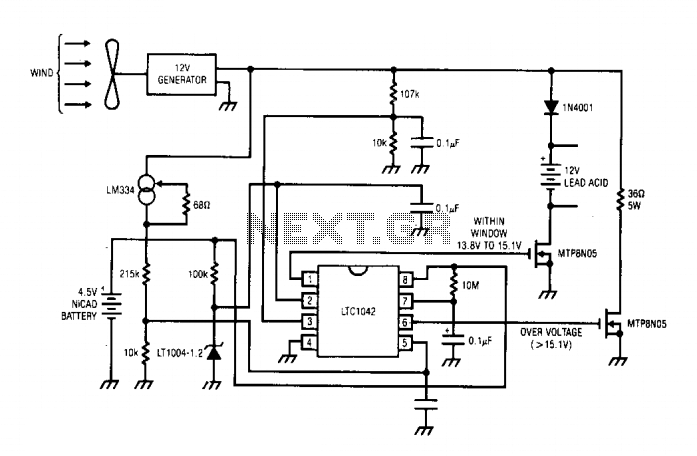
The DC motor operates as a generator, with the voltage output being directly proportional to its RPM. The LTC1042 monitors this voltage output and provides various control functions. When the generator voltage output falls below 13.8 V, the control...