
Dual Adjustable/Variable Power Supply Circuit Using LM 317 & LM337

The dual adjustable power supply circuit utilizes the LM317 and LM337 voltage regulators to provide a versatile output voltage that can be adjusted between 1.2 volts and 30 volts. The LM317 is a positive voltage regulator, while the LM337 serves as a negative voltage regulator, allowing for both positive and negative outputs from a single power supply configuration.
The circuit typically consists of the following components: the LM317 and LM337 integrated circuits, a transformer to step down the AC voltage to a suitable level, rectifier diodes to convert AC to DC, filter capacitors to smooth the output voltage, and adjustable resistors (potentiometers) to set the desired output voltage level.
For the positive output, the LM317 requires a minimum input voltage that is approximately 3 volts higher than the desired output voltage. The output voltage can be adjusted using a pair of resistors connected to the adjustment pin of the LM317. The formula for the output voltage (Vout) is given by Vout = 1.25V * (1 + R2/R1), where R1 is the resistor connected between the output and the adjustment pin, and R2 is the resistor connected from the adjustment pin to ground.
Similarly, the LM337 operates with a similar configuration for the negative voltage output, where the output voltage can also be adjusted using a pair of resistors. The output voltage formula for the LM337 is Vout = -1.25V * (1 + R2/R1).
The circuit design may also incorporate additional features such as short-circuit protection, thermal shutdown, and indicator LEDs to show the status of the output voltages. Heat sinks may be used on the LM317 and LM337 to dissipate heat generated during operation, especially when delivering higher currents.
This dual adjustable power supply circuit is suitable for various applications, including powering operational amplifiers, sensors, and microcontrollers that require stable and adjustable voltage levels. Proper layout and grounding techniques should be employed to minimize noise and improve performance in sensitive applications.Dual adjustable power supply circuit with diagram using IC LM 317 and LM 337. This variable power supply circuit has a range of 1.2 Volts to 30 Volts.. 🔗 External reference
Related Circuits
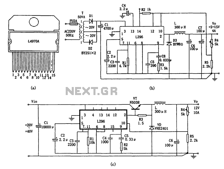
The L296 chip is a high-current switching power supply component designed to operate within a voltage range of 5 to 15V and provide an output current of up to 4A. This monolithic chip incorporates several features including enhanced protection...
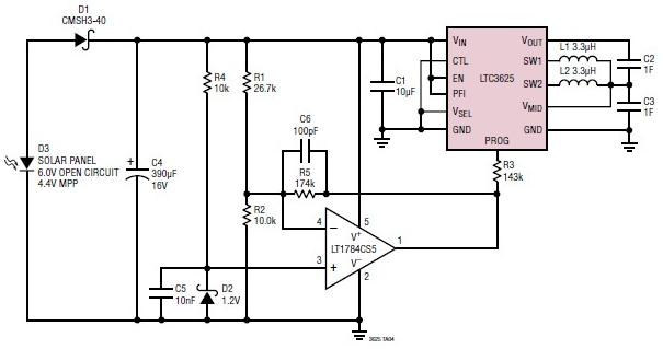
A simple supercapacitor charger electronic project can be designed using the LTC3625 integrated circuit (IC) from Linear Technology. This circuit is capable of charging two supercapacitors in series to a fixed output voltage of either 4.8V/5.3V or 4V/4.5V, which...
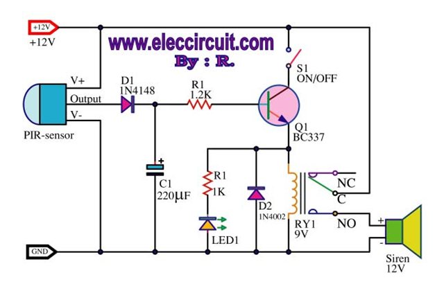
A motion detection alarm circuit utilizing a PIR sensor for motion detection. When movement is detected by the PIR sensor, it triggers a delay circuit, Q1, and other components. The motion detection alarm circuit is designed to provide an alert...
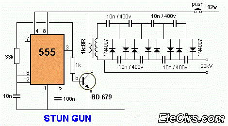
A 12V to 20000V inverter circuit diagram (stun gun) is presented. This circuit generates a very high voltage and must be used with caution to prevent electric shock. The transformer can produce over 1000V and amplify the voltage by...
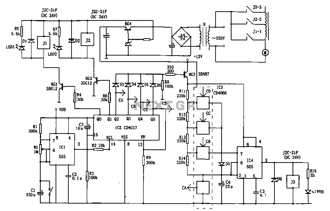
The AC welder operates intermittently, with power consumption during these periods reaching several hundred watts. The AC welder saving controller circuit enables the welding machine to automatically cut off power during no-load conditions while also automatically restoring power for...
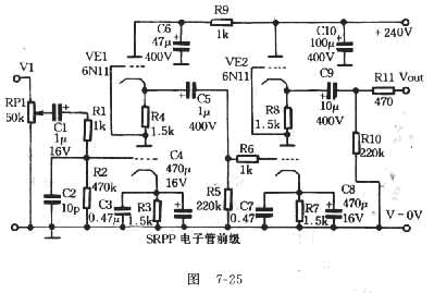
The FET amplifier is designed for enthusiasts who prefer tube sound but cannot utilize traditional tube amplifiers. It exhibits output characteristics similar to bipolar FET tube amplifiers, featuring good frequency response and sound quality comparable to tube amplifiers. Coupling...