
12V Regulated Inverter Supply

The circuit employs a step-up inverter design to ensure stable voltage output for sensitive electronic devices powered by lead-acid battery banks. The inverter uses two transistors (Q1 and Q2) configured in a push-pull arrangement to generate a square wave AC signal from the DC input. The ferrite pot-core transformer is crucial for stepping up the voltage; its turns ratio is engineered to optimize the output voltage while maintaining efficiency.
The output from the transformer is rectified using diodes D4 and D5, allowing the AC signal to be converted back into a DC signal. This rectified voltage is then combined with the input voltage to create a higher DC voltage that is fed into the 7812 voltage regulator. The 7812 regulator is a linear voltage regulator that maintains a steady 12V output, capable of delivering up to 1.5A. When higher current is required, a more robust linear regulator can be substituted without significant redesign, allowing the circuit to accommodate loads up to 5A.
Diodes D2 and D3 serve to protect the circuit from reverse voltage conditions, while D6 is a protection diode that prevents potential damage to the regulator and the connected load. The design also allows flexibility in the output voltage levels. By modifying the transformer’s turns ratio and selecting an appropriate linear regulator, the circuit can be adapted to power devices requiring 24V or other voltage levels, such as laptops needing approximately 18V.
The winding of the transformer is critical for the performance of the inverter. The bifilar winding technique used for L1, L2, L3, and L4 ensures that the inductance is balanced, which is essential for effective operation. The use of 1mm-diameter enameled copper wire is specified to handle the current requirements while minimizing resistive losses.
Overall, this circuit design provides a reliable method for powering 12V electronic devices from lead-acid batteries, addressing the issues of voltage fluctuation and ensuring compatibility with a range of appliances.When running 12V electronic devices from lead-acid battery banks, the voltage to the appliance can vary from below 11V with discharged batteries, to well above 14V during charging. Many appliances will not tolerate such a wide fluctuation and may perform poorly or be damaged. This step-up inverter, combined with a 12V fixed regulator, is a good so lution. Q1 & Q2, together with the ferrite pot-core transformer, comprise a DC-to-AC inverter. The turns ratio steps down the input voltage by about 30%. The square wave output voltage is rectified and added to the input DC voltage. The stepped up DC is then fed to a 7812 12V regulator (REG1). The specified regulator will supply 1. 5A at 12V out, from any input into the inverter between 9V and 15V, with the inverter making up the shortfall. Current requirements are kept to a minimum by not having the inverter supplying the total current. By substituting a higher rated linear regulator, up to 5A can easily be supplied by this simple circuit.
The transistors can be almost any general-purpose power type while the twin diode (D4/D5) is a high-speed device commonly found in defunct computer power supplies. Normal rectifier diodes can be used with a slight decrease in efficiency. The same comment applies to D2/D3. D6 is a protection diode and any 3A type will be suitable. By slightly modifying the turns ratio, and substituting the linear regulator, 24V devices can be operated from a 12V supply.
Laptops requiring around 18V can be powered as well. This diagram shows how to wind the transformer. L1 & L2 are six turns bifilar wound using 1mm-diameter enameled copper wire, while L3 & L4 are four turns bifilar wound. 🔗 External reference
Related Circuits
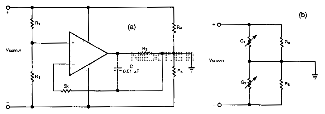
This simple circuit can convert a single supply voltage, such as a battery, into a bipolar supply. Sense resistors R1 and R2 establish relative magnitudes for the resulting positive and negative voltages. Their rail-to-rail value equals V_SUPPLY. Resistors R4...
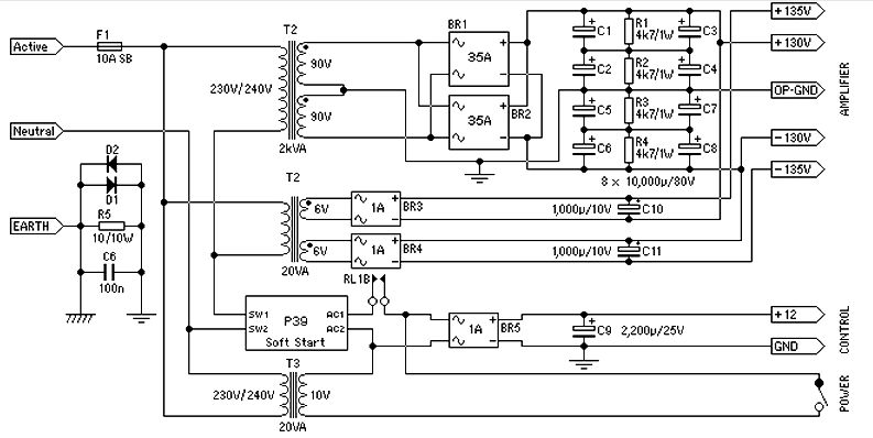
Power supply for a 1500-watt audio power amplifier. This power supply circuit is paired with a high-power audio amplifier rated at 1500 watts. A serious approach is required to design the power supply for the amplifier. First, a step-down...
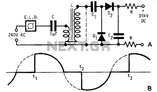
A light dimmer, a 1 µF capacitor, and a 12 V car ignition coil form a simple line-powered high-voltage generator. The current in the dimmer is illustrated in Fig. B. During the time intervals tp to t2, determined by...
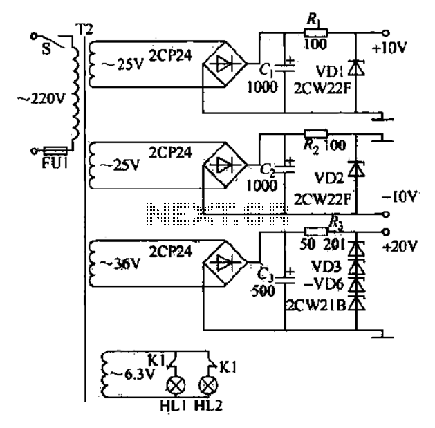
DC power supply with a shunt, rectifier, filter, limiter, and regulator. The circuit is simple and cost-effective, capable of meeting the requirements. The 6.3V indicator lights HL1 and HL2 indicate the lathe's running and stopping status through a relay...

A simple yet effective circuit to generate a POTS-compatible ringing voltage can be constructed using National Semiconductor's LM4871 audio amplifier IC along with a dozen passive components. This circuit produces a sine-wave output of 1 W at approximately 70...
Wibowa Chou from IR discusses the benefits of fourth-generation IGBTs compared to MOSFETs, particularly in the context of a practical solar inverter application. Fourth-generation Insulated Gate Bipolar Transistors (IGBTs) offer significant advantages over Metal-Oxide-Semiconductor Field-Effect Transistors (MOSFETs) in various applications,...