
CF1 CF2 DC power supply circuit

The described circuit is a DC power supply designed for versatility in various applications, particularly in powering equipment like lathes. The power supply incorporates several key components to ensure stable and reliable operation.
The shunt resistor is utilized to measure current, providing feedback for the system to maintain proper output levels. The rectifier converts the incoming AC voltage to DC, ensuring that the output is suitable for sensitive electronic components. Following the rectification, a filter circuit smooths the output voltage, reducing ripple and providing a more stable DC signal.
To protect the circuit and maintain the desired output voltage, a limiter is included. This component prevents the voltage from exceeding specified levels, safeguarding downstream components from potential damage. The regulator further stabilizes the output voltage, ensuring that it remains constant despite variations in input voltage or load conditions.
The indicators HL1 and HL2, which operate at 6.3V, are crucial for user feedback. They visually signal the operational status of the lathe. HL1 indicates that the lathe is running, while HL2 signals that the lathe has stopped. These indicators are controlled by a relay circuit, which allows for remote operation and automation of the lathe's functions.
Overall, this DC power supply circuit is designed with simplicity and cost-effectiveness in mind, making it suitable for a range of applications while providing essential functionality and user feedback.DC power supply: DC power supply with shunt, the rectifier, filter, limit, the regulator points jsIJ ~ string disabilities 10V, the circuit is simple. Cost low, can meet the re quirements, the figure 6.3V indicator HL1, HL2, indicate lathe running and stopping, by the relay control circuit.
Related Circuits
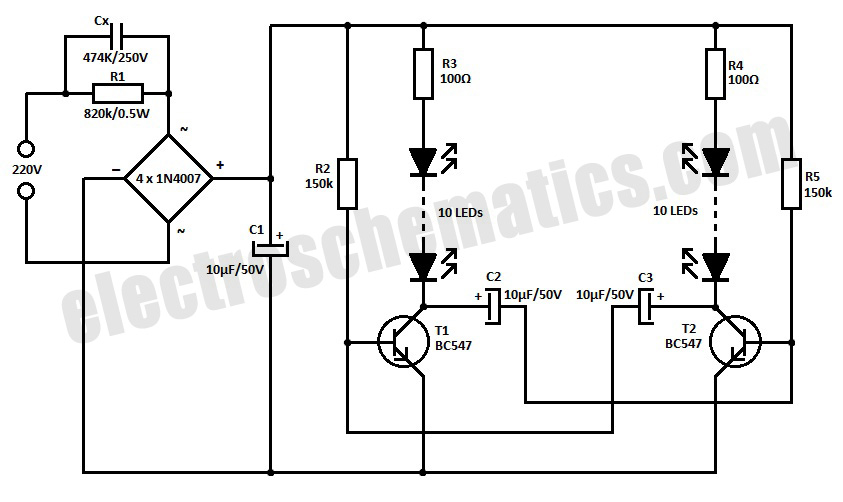
This is a simple LED blinker or flasher designed for decorative purposes. The circuit features 20 high-brightness LEDs that flash alternately, creating a vibrant color display. The LED blinker circuit typically consists of several key components including a microcontroller or...
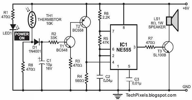
The following circuit illustrates a fire alarm circuit diagram utilizing the NE555 integrated circuit (IC). Features include functioning as a heat sensor and incorporating a 10 kilo-ohm resistor. The fire alarm circuit based on the NE555 IC is designed to...
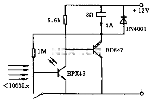
In the circuit's resting (dark) state, current flows through the electromagnet M. When light shines on the phototransistor, it turns on, causing the final stage transistor to enter the OFF state, which releases the solenoid. A 1M ohm feedback...

A pH electrode measures hydrogen ion (H+) activity and generates an electrical potential or voltage. The operation of the pH electrode is based on the principle that an electric potential develops when two liquids of different pH come into...
TV video signal processor circuit. The ECG1064 chip includes a primary video amplifier, two sync pulse amplifiers, a look-out protector, a noise detector, two noise gates, an automatic gain control (AGC) detector, an intermediate frequency (IF) AGC amplifier, a...
An additional push-button switch is typically required for the ATX Power Switch/Soft Power Switch signal; however, this simple circuit eliminates that need. The design is effective and has undergone extensive testing. A zener diode is included to protect against...