
Dc motor speed controller circuit using NE555

The described circuit utilizes the NE555 timer IC in astable or monostable mode to control the speed and direction of a DC motor. In the astable configuration, the NE555 generates a PWM (Pulse Width Modulation) signal, which is used to vary the average voltage supplied to the motor, thereby controlling its speed. The duty cycle of the PWM signal can be adjusted by changing the resistance and capacitance in the timing network connected to the NE555.
For direction control, an H-bridge configuration is often employed. This arrangement allows the current to flow through the motor in either direction, enabling forward and reverse operation. The control signals for the H-bridge can be derived from the outputs of the NE555 timer or from additional control circuitry, such as a microcontroller or manual switches.
Key components of the circuit include the NE555 timer, resistors, capacitors, an H-bridge driver (such as the L298 or L293D), and the DC motor itself. Proper selection of component values is crucial for achieving the desired speed range and responsiveness of the motor control. Additionally, protective elements like diodes may be included to prevent back EMF from damaging the circuit when the motor is turned off.
Overall, this DC motor controller circuit provides a flexible solution for controlling the speed and direction of a DC motor, suitable for various applications in robotics, automation, and hobby projects.A DC motor controller based on NE555 timer is shown here. Direction of rotation of DC motor can be also changed by this DC motor speed control circuit.. 🔗 External reference
Related Circuits
It is a single integrated circuit that includes EEPROM, RAM, an analog-to-digital converter, numerous digital input and output lines, timers, and a UART for RS-232 communication, among other features. A complete programming environment is available for Linux, allowing programming...
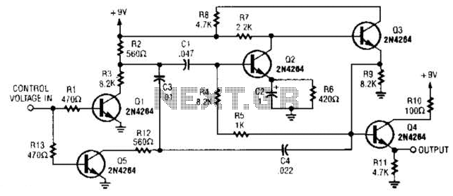
A DC control voltage varies the effective resistance in the feedback network consisting of capacitors C4, C3, C1 and resistors R12, R3. Additionally, Q2 and Q3 serve as the oscillator transistors. The circuit operates by utilizing a DC control voltage...
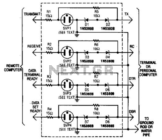
This modem/fax protector can be utilized in telephone-line connections between a PC or a terminal and a remote computer. In this circuit, the surge voltage protectors (SVPs) are rated at 230 V. Additionally, a proper grounding is essential for...
This is an economical 150 Watt amplifier circuit that utilizes two complementary Darlington power transistors, TIP 142 and TIP 147. It is capable of delivering a robust 150 W RMS to a 4 Ohm speaker, offering significant audio output....
The FM modulator circuit, which utilizes frequency modulation, is constructed using a Motorola MC1648P oscillator. Two varactors, specifically Motorola MV-209, are employed to modulate the frequency of the oscillator. A 5000-ohm potentiometer is incorporated to bias the varactors for...

This design outlines a high impedance DC voltmeter circuit utilizing the uA741 integrated circuit (IC). The uA741 is configured as a non-inverting DC amplifier. The circuit incorporates negative feedback through a DC meter that requires 1 mA for full-scale...