
80 mhz 108 mhz fm transmitter circuit

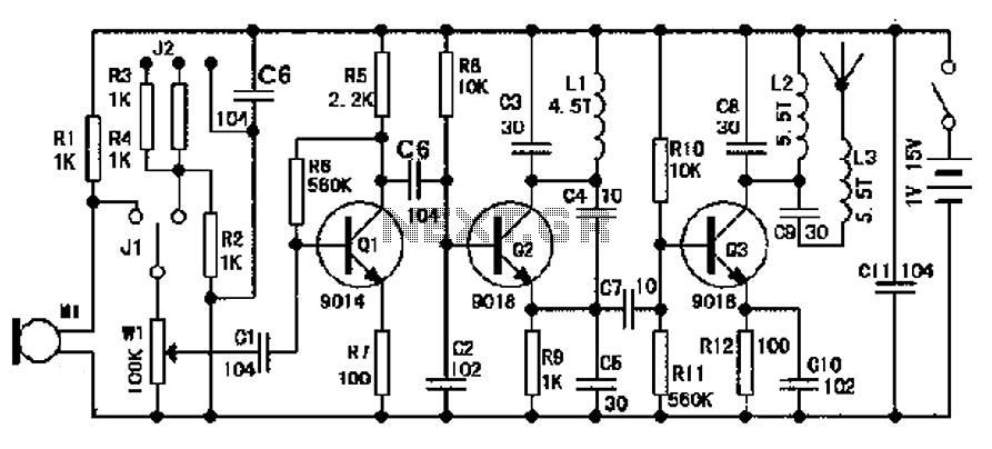
The FM transmitter circuit primarily consists of two 2N2222 transistors, which serve as the main amplification elements. The first transistor (Q1) is responsible for amplifying the audio signals captured from the microphone. The second transistor (Q2) acts as a modulator, mixing the amplified audio signal with the carrier frequency generated by the LC circuit composed of capacitor C5 and inductor L1. The design ensures that the audio signal is superimposed onto the carrier wave, effectively modulating it for transmission.
The LC circuit determines the operating frequency of the transmitter, which is crucial for tuning the device to the desired FM band. The construction of L1 is critical; it should consist of 24 turns of insulated wire wrapped around a cylindrical form, allowing for proper inductance values that enable operation within the specified frequency range of 80 MHz to 108 MHz. The length of the antenna, which should be ideally between 8 to 12 inches, is also essential for efficient transmission and compliance with FCC regulations.
The power supply for the FM transmitter is a 9-volt battery, providing sufficient voltage for the transistors to operate effectively. It is important to ensure that all components are rated appropriately for the voltages and currents involved in the circuit to prevent damage and ensure reliability.
For practical assembly, the circuit layout should be designed to minimize interference and ensure stable operation. Proper grounding and shielding techniques should be employed to prevent signal degradation and maintain the integrity of the transmitted signal. Additionally, the circuit should be tested in a controlled environment to ensure compliance with legal regulations regarding frequency use. Overall, this FM transmitter serves as an excellent educational tool for understanding basic RF transmission concepts and the functioning of transistor amplifiers.FM transmitter or often called fm transmitter uses 2 transistors in this article uses 2 transistors 2n2222. If the fm transmitter is in use voltage supply of 9 volt battery and use an antenna whose length is less than 12 inches, then this fm transmitter will be within FCC limits.
Signals from the microphone in the fm transmitter is reinforced by Q 1, Q2 with carrier frequency generator is determined by the C5 and L1. The frequency of the FM transmitter is in the range 80 MHz - 108 MHz. L1 can be made with as many as 24 e-mail wire wrap and 6 wrap. The following is a picture series for the fm transmitter fm transmitter referred to in article 2 of this transistor. This fm transmitter antenna is connected to the mid point of the antenna length L1 and preferably between 8-12 inches.
FM Transmitter is only used for experiment and learning materials are not to be used for day-to-day, because the use of FM transmitter frequency regulated and protected by law may be understandable. 🔗 External reference
Related Circuits
A touch switch is a switch that is turned on and off by touching a wire contact, instead of flicking a lever like a regular switch. Touch switches have no mechanical parts to wear out, so they last a...
L1 is 0.112uH (this tunes to the middle of the FM band, 98 MHz, with VC1 at its centre value of 33pF). L1 is 5 turns of 22 swg enamelled copper wire close-wound on a 5mm (3/16") diameter former....
The modular Portable Mixer design presented on these web pages has gained popularity among many amateurs. However, some users have requested a simpler device specifically for mixing mono signals. This revised design aims to meet those requirements, incorporating three...
The design of an FM radio transmission frequency band enables compatibility with any FM radio receiver, allowing the high-frequency signal to be transmitted and restored from an audio signal. This technology serves various applications. Applications of a wireless microphone...
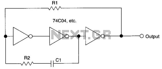
This circuit employs a protective resistor R2 along with a feedback resistor R1. Together, these components create a voltage divider that lowers the input voltage amplitude for IC1-a, ensuring that the protective diodes remain inactive. This arrangement enhances the...
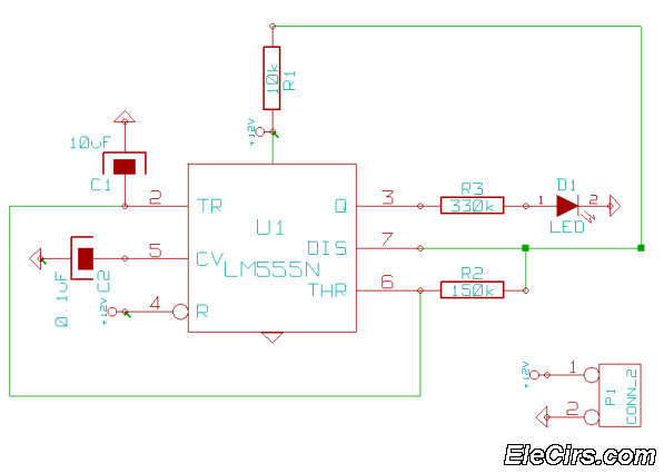
This is a very simple 555 timer circuit that serves as a straightforward theft deterrent, which may be just as effective. The idea is to have a flashing red LED indicate that your car is protected. This device can...