
14MHz SSB 10mW transceiver

The "OZL type" transceiver is a compact, single conversion superheterodyne device designed for efficient communication. The architecture employs two double-balanced mixers (DBMs), which serve dual roles as both modulator and demodulator, enhancing versatility in signal processing. The modulator DBM operates during transmission, converting baseband audio signals into radio frequency (RF) signals, while during reception, it reverses this process to demodulate incoming RF signals back into audio.
The design incorporates amplifiers that are active in both transmitting and receiving modes, ensuring optimal signal strength and clarity. This dual functionality is critical for maintaining effective communication over varying distances and conditions. The physical housing of the transceiver repurposes components from a previously non-functional 10W 7MHz transmitter, demonstrating a sustainable approach to electronics by reusing materials that would otherwise be discarded.
The use of "Magic ink" for decals indicates a straightforward yet effective method for labeling and branding the device, enhancing usability without complicating the construction process. The standard operating voltage for the "OZL type" is typically sourced from a 12V DC supply, such as that found in automotive applications via a cigarette lighter. However, this specific design variant utilizes a 20V DC power supply, which serves a dual purpose: it allows for the adjustment of the variable capacitor within the VXO (Voltage Controlled Crystal Oscillator) to achieve its minimum capacitance, thereby facilitating the generation of higher frequencies. This choice of higher voltage reflects an understanding of the relationship between voltage and frequency performance in oscillator circuits, ultimately enhancing the transceiver's operational capabilities.The whole Construction : You can call the transceiver like this as "OZL type". Characteristics of the "OZL type" are as follows. 1. Single conversion super. 2. Using two DBM-s as modulator and converter. 3. Modulator DBM is used as demodulator in receiving time. 4. All amplifiers are used in transmitting and receiving time. 5. Case is second use of my failed or useless machine.(This time I used my useless old 10W 7MHz transmitter.) 6. All decals are done with the "Magic ink". Very simple way! 7. Normal "OZL type" uses 12V DC power from cigar lighter of the car. But in this machine I used 20V DC from my DC power supply. The reason of my choosing high voltage are as follows. One reason is in order to press the variable capacitor of the VXO oscillator for it`s minimum capacitance and to get the highest frequen 🔗 External reference
Related Circuits
Several RS232 transceiver circuits are used for communication between microcontrollers and other devices, such as PCs or RS232 devices. This document presents a collection of well-known RS232 transceiver circuits. The circuit utilizes the MAX232 from Maxim's devices, which is...
In general, the transceiver switches the 4-element 1500 ohm xtal BPF ends between the inputs and outputs of the two SA602s to reverse the signal flow for R/T operation. Since no IF amplifier is used in the design, 20...
This simple QRP transceiver for the 30 m band did not result from a detailed requirement profile. I simply had some NE592 broadband amplifiers in my junk box, waiting for an application. After performing some tests, that application was...
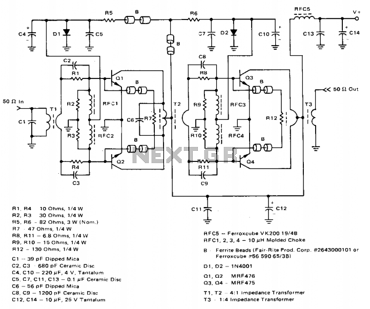
The amplifier achieves a total power gain of approximately 25 dB, utilizing a construction technique that incorporates low-cost components throughout. The MRF476 is rated as a 3-watt device, while the MRF475 delivers an output power of 12 watts. Both...

The 7MHz CW transceiver is constructed using the MC3362P integrated circuit, originally intended for a 10MHz band transceiver. Due to concerns regarding unexpected neighboring spurious signals, the frequency was altered to 7MHz, leading to the completion of the transceiver....
This is a rather unusual QRP Power Amplifier design, with a wide frequency response; within three dB's from 300KHz to 30MHz. Overall gain is in the region of 16dB and the final output power may be well over four...