
150MHz to 170MHz in 25kHz steps using a LMX2306 PLL

The PLL design process using SimPLL's PLL Wizard streamlines the creation of a versatile and efficient PLL configuration. The LMX2306 PLL IC, known for its low phase noise and wide frequency range, works in conjunction with the MiniCircuits POS300 VCO, which provides stable frequency output. The design's loop bandwidth of 2.5 kHz ensures that the system can respond effectively to frequency changes while maintaining stability. The phase margin of 45 degrees is a critical design criterion, as it balances stability and transient response.
The phase detector current settings play a significant role in the performance of the PLL. The comparison between the 250 µA and 1 mA settings highlights the impact of current on the loop filter's effectiveness in minimizing phase noise and achieving stable locking. The analysis of DC current effects at the phase detector reveals potential sources of noise that can degrade performance, emphasizing the importance of careful component selection and layout in PLL design.
The modulation frequency response illustrates how the PLL responds to changes in input signal frequency, with the observed peaking indicating the sensitivity of the system around its bandwidth. The settling time data provides valuable insights into the speed of the PLL's response to input frequency changes, which is crucial for applications requiring rapid frequency adjustments.
The lock detect filter outputs demonstrate the differences between analog and digital lock detection methods, providing insight into the PLL's operational status. The ability to customize design parameters and generate detailed reports enhances the design process, allowing engineers to optimize performance based on specific application requirements.
In summary, the SimPLL PLL Wizard offers a powerful platform for designing and simulating PLLs, enabling rapid development and optimization of high-performance frequency synthesis solutions in various electronic applications.Using SimPLL`s new PLL Wizard you can design a new PLL with a few clicks of the mouse. We have just designed one that tunes from 150MHz to 170MHz in 25kHz steps using a LMX2306 PLL IC and a MiniCircuits POS300 VCO. and because the LMX2306 and MiniCircuits POS300 are in the libraries, you haven`t had to enter any device data.
The PLL has been desig ned with a loop bandwidth of 2. 5kHz and a phase margin of 45degrees. SimPLL predicts the phase noise from the synthesizer. To evaluate which phase detector current setting to use we compared the 250uA setting (red trace) to the 1mA setting (blue trace), both with a loop bandwidth of 2. 5kHz. The difference is due to the larger loop filter resistor in the low current case. Showing the effect of 1nA of DC current at the phase detector. This could be from phase detector leakage, in some cases from loop filter capacitor leakage or VCO varactor diode leakage.
Modulation frequency response from modulating the VCO, showing the peaking around the loop bandwidth. Blue trace is with a 45 degree phase margin, red trace has a 60 degree phase margin to reduce peaking.
Loop settling is easily observed on the plot of |frequency error|. This shows at a glance that the loop takes about 1. 1ms to lock to within 1kHz and 1. 5ms to lock within 10Hz The VCO phase error is an important parameter in many digital communications systems - here we can see that for the transient plotted above, the VCO takes about 1. 1ms to lock to within 10 degrees of its final phase. SimPLL even provides you with details of the output of the lock detect filter. Shown here in the blue trace is the output from the two time constant analog lock detect filter shown in the schematic, the red trace is the lock detect output using the LMX2306 digital lock detect circuit.
You can vary any of the design parameters (such as loop bandwidth, phase margin, charge pump current etc) or component values and watch how the PLL performance changes. Add to this is a report that you can customize to provide phase noise details, phase jitter calculations, residual FM, ACI and ACR calculation.
SimPLL even designs and simulates PLL`s using switched loop filters for faster locking. SimPLL will have you optimising designs in minutes that you had to build and measure before. 🔗 External reference
Related Circuits
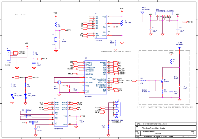
IperCODE is an educational project that enables the construction of a remote control acquisition system utilizing rolling code technology. It allows for the transmission of the received code via an RS232 serial port, the visualization of the code on a...
This project focuses on the development of a low-cost cosmic ray detector utilizing common fluorescent tubes. It is based on an experiment conducted in 2000 by Dr. Schmeling at CERN, which demonstrated a straightforward method for detecting and visualizing...
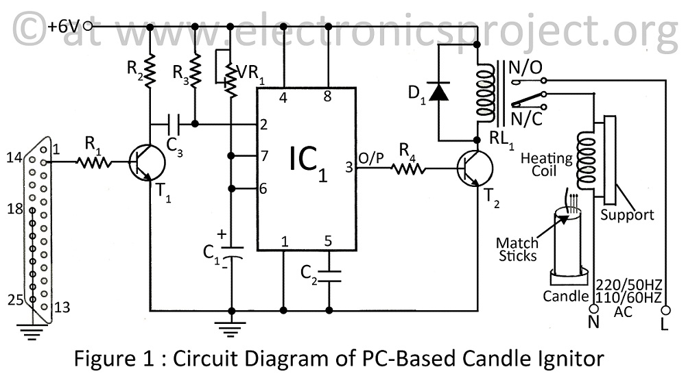
A PC-based candle ignitor is a verified project designed for computer students, utilizing a 555 timer circuit to ignite a candle. The project includes a computer circuit diagram and software code written in C. The PC-based candle ignitor project integrates...
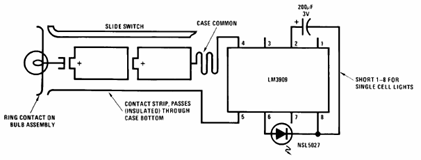
The schematic presented below illustrates the Flashlight Finder circuit diagram utilizing the LM3909, a monolithic oscillator specifically designed for flashing Light Emitting Diodes (LEDs). The Flashlight Finder circuit employs the LM3909 integrated circuit, which is capable of generating a series...
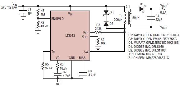
A straightforward dual 15-volt power supply electronic circuit can be created using the LT3512 switching regulator IC produced by Linear Technology. This basic 15-volt DC power supply operates with an input voltage range of 36 to 72 volts and...
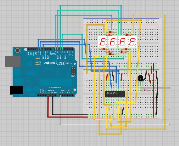
The intention is to utilize this code in future projects involving 7-segment displays. For those interested in learning more about 7-segment displays, additional information can be found in a related post. 7-segment displays are widely used in electronic devices for...