
15 volts power supply electronic circuit project using LT3512

The dual 15-volt power supply circuit utilizing the LT3512 switching regulator is designed to efficiently convert a higher input voltage into a stable dual output voltage. The LT3512 is a versatile, high-performance switching regulator that is capable of handling input voltages between 36 and 72 volts, making it suitable for various applications where such voltage levels are present.
The circuit configuration typically includes the LT3512 IC, which is the core component responsible for voltage regulation. The output voltage is set to 15 volts by selecting appropriate feedback resistors that determine the gain of the feedback loop. The maximum output current of 0.2 A is sufficient for many low to moderate power applications, such as powering analog circuits, sensors, or small microcontrollers.
Additionally, the circuit may include a few external components such as input and output capacitors, inductors, and diodes. Input capacitors are necessary to filter the input voltage and stabilize the power supply, while output capacitors help smooth the output voltage and reduce ripple. The inductor is crucial for energy storage and transfer during the switching process, and the diode is used to prevent reverse current flow, ensuring the safety and reliability of the circuit.
The simplicity of this design, coupled with the high efficiency of the LT3512, makes it an attractive choice for engineers and hobbyists looking to create a reliable dual 15-volt power supply. The compact nature of the circuit allows it to be integrated into various electronic projects where space is a constraint, and its efficiency means less heat generation, which is vital for maintaining the longevity and performance of electronic components. Overall, this power supply circuit stands out as an effective solution for applications requiring dual voltage outputs with minimal component requirements.A very simple dual 15 volts power supply electronic circuit project can be designed using the LT3512 switching regulator IC manufactured by Linear Technology. This simple 15 volts DC power supply electronic project operates from an input voltage range of 36 to 72 volts and delivers a dual 15 volts output at a maximum current of 0.
2A. As you can see in the schematic circuit diagram, this electronic circuit project require few external electronic parts and can be used for powering electronic circuits where is required a high efficiency. 🔗 External reference
Related Circuits
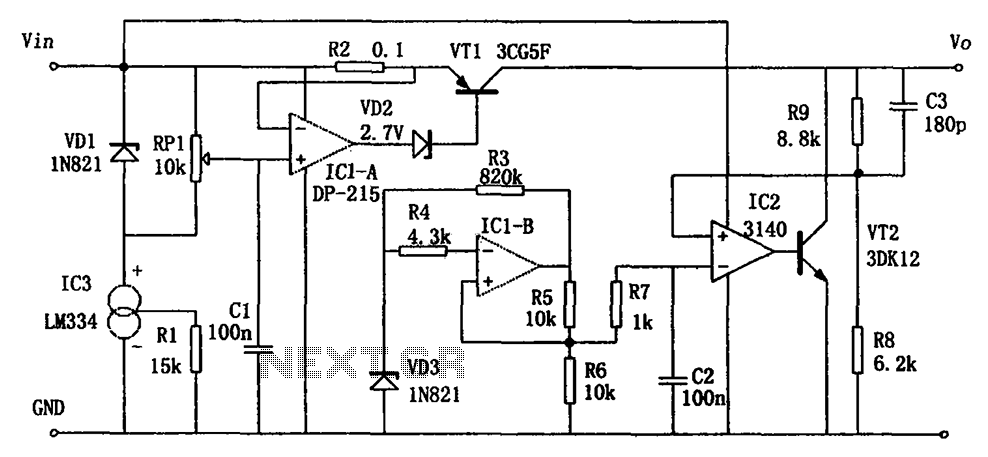
The circuit functions as a switching power supply designed to operate alongside a linear regulated power supply. Key characteristics include high efficiency and low dropout voltage. It effectively filters out high-frequency ripple voltage and manages instantaneous voltage variations, making...
The modular Portable Mixer design presented on these web pages has gained popularity among many amateurs. However, some users have requested a simpler device specifically for mixing mono signals. This revised design aims to meet those requirements, incorporating three...
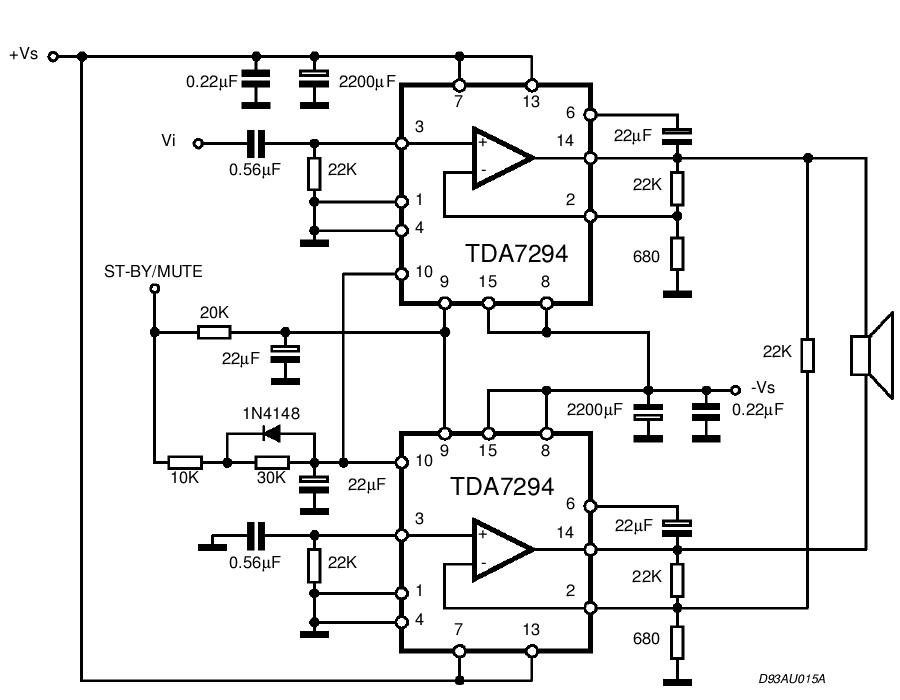
The TDA integrated circuit series is highly regarded and widely utilized in amplifier designs and projects. TDA audio amplifier circuits are primarily produced by Philips and SGS-THOMSON. The most commonly used ICs include the TDA2030 and TDA2003 for small...
The bicore is the basis of advanced BEAM. Most intermediate to advanced BEAM robots are built off of the bicore. Uses go all the way from photovores to servo motor drivers to walkers. What it is is basically just...
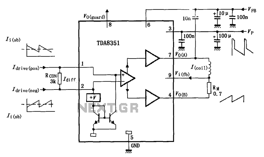
The figure illustrates the actual application circuit for the TDA8351/8356. In this circuit, a 50V voltage feedback (VFB) is connected in series with a 33-ohm resistor. Signals are input at pins 1 and 2, where pin 1 receives a...
This charger is based on a charging voltage of 2.4 volts per cell, in accordance with most manufacturers' recommendations. This circuit pulses the battery with 14.4 volts (6 cells x 2.4 volts per cell) at a rate of 120...