
IperCODE - HowTo Build a Remote Control Using Rolling Code

The IperCODE project incorporates a microcontroller to facilitate the acquisition and processing of the rolling code signals. The system typically begins with a remote control that transmits a unique rolling code, which is received by a dedicated RF module. The received signal is then processed by the microcontroller, which decodes the rolling code and prepares it for further actions.
For data transmission, the microcontroller interfaces with an RS232 module, allowing the decoded code to be sent to a connected device, such as a computer or another microcontroller. This feature is particularly useful for applications that require logging or monitoring of the received codes.
The project also includes a 16x2 LCD display, which serves as a user interface. The microcontroller drives the display to show the received rolling code in real-time, providing immediate feedback to the user. This display functionality can be enhanced with additional features, such as scrolling text or error messages, depending on the complexity of the implementation.
Overall, the IperCODE project serves as an excellent educational tool for understanding remote control systems, rolling code technology, and serial communication protocols, while also providing practical experience in microcontroller programming and interfacing with peripheral devices.IperCODE is a didactic project, with which it is possible to build a remote control acquisition system, based on the rolling code and to have the possibility to transmit the received code on RS232 serial port, to visualize it on the 16X2 display or to reproduce it 🔗 External reference
Related Circuits
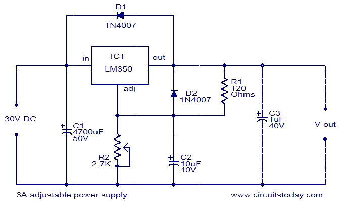
This circuit diagram illustrates a 3A adjustable power supply utilizing the LM350K integrated circuit. The LM350K is a robust voltage regulator IC that features thermal regulation and short circuit protection. The design adheres to application notes provided in the...
This transmitter emits an FM signal within the 88 to 108 MHz frequency range, featuring a tone of 19 kHz. It is designed to activate the FM MPX pilot carrier indicator, enabling interfacing with external devices. L4 is intended...
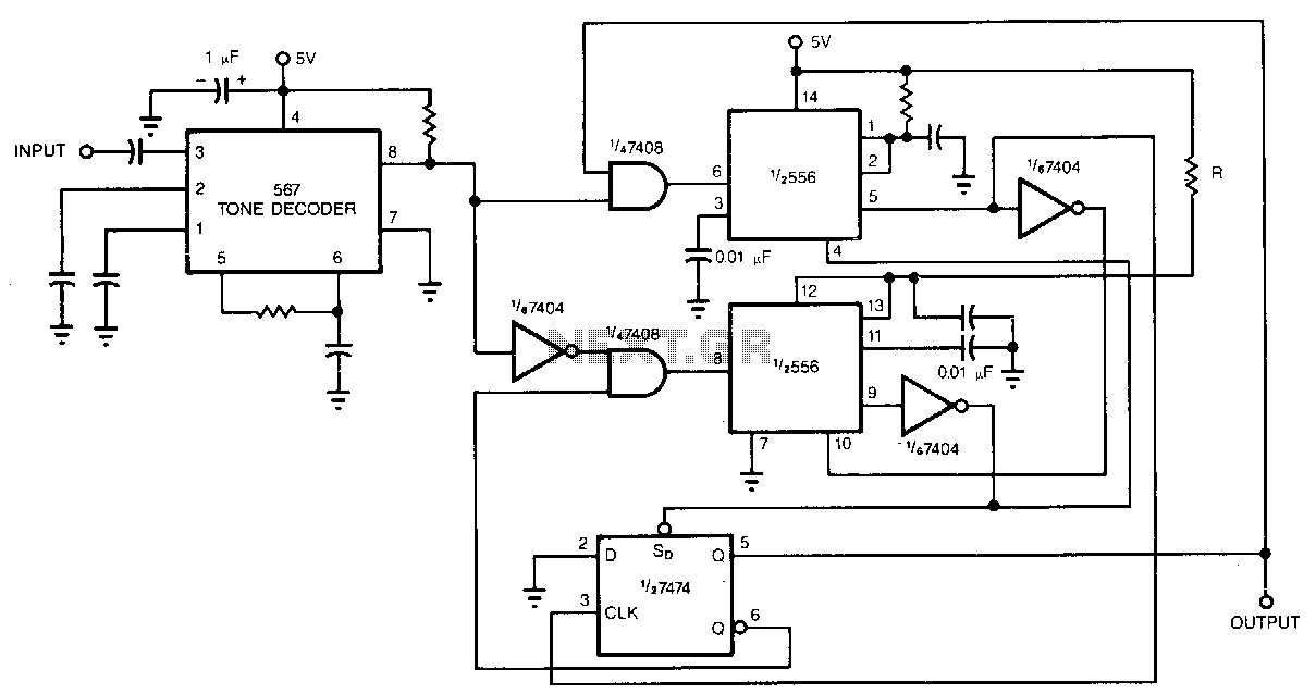
Adding a pair of monostable multivibrators to the output of a 567 tone decoder reduces its sensitivity to out-of-band signals and noise. In the absence of these multivibrators, the 567 is susceptible to unwanted output chatter. Alternative protection methods,...
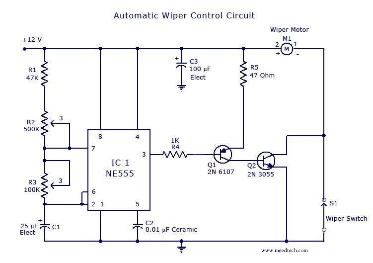
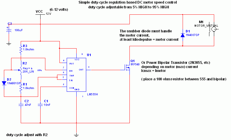
The circuit is built around an astable multivibrator using the NE555 timer. The output at pin 3 remains high for a duration determined by resistor R2 and low for a duration set by resistor R3. The low output pulse...
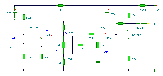
The following circuit illustrates the BC 109C used in a tone control circuit diagram. Features include attenuation of all audio frequencies and high input impedance. The BC 109C transistor is a versatile component often utilized in audio applications, particularly in...
The 555 IC is configured in an astable mode, producing a frequency that remains constant and is independent of the duty cycle. The total resistance (Rcharge + Rdischarge, considering the diode) is fixed at 22 kΩ, yielding a frequency...