
150mW Crystal AM Transmitter PCB

The circuit design features a crystal oscillator as its fundamental element, crucial for maintaining precise frequency stability necessary for effective radio transmission. The 10MHz crystal oscillator provides the carrier frequency, which is essential for modulating the audio signal captured by the condenser microphone. The amplification stage, consisting of transistors Q1, Q2, and Q3, ensures that the audio signal is sufficiently boosted to effectively modulate the RF carrier.
Transistor Q4, functioning as the oscillator, plays a pivotal role in generating the RF signal. The modulation process occurs at the collector of Q4, where the audio signal alters the amplitude of the RF carrier, resulting in an AM signal. This AM signal is subsequently transmitted through the antenna system. The choice of a matching dipole antenna, in conjunction with coaxial cable, optimizes the transmission efficiency and range. The external wire antenna further enhances the circuit's performance, allowing for extended transmission distances.
The power supply, ranging from 9V to 12V, is critical for the operation of the circuit, providing the necessary voltage for the transistors and oscillator. The modulation transformer (X1) is a key component for coupling the audio signal to the RF carrier. Utilizing an audio output transformer from older transistor radios is a practical solution, while constructing one from E/I core laminations allows for customization to suit specific requirements. The specified windings—40 turns of 26 SWG wire for the inner winding and 200 turns of 30 SWG wire for the outer winding—facilitate the appropriate impedance matching for effective signal transfer.
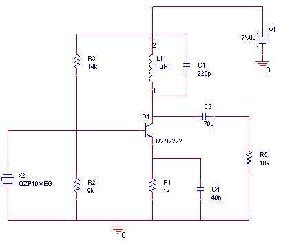
Overall, this circuit design exemplifies a straightforward yet effective approach to AM transmission, integrating essential components to achieve reliable performance in audio signal modulation and transmission.The heart of this circuit is a crystal oscillator. A 10MHz crystal is used to produce highly stable carrier frequency. The sound signal from the condenser mic is amplified by the amplifier circuit consist of transistors Q1, Q2 and Q3. The amplified audio signal modulates the RF carrier generated by the crystal oscillator built around transistor Q4
. Here, modulation is done via the power supply source line. The amplitude modulated (AM) signal is obtained at the collector of oscillator transisitor Q4. The use of matching dipole antenna and co-axial cable, the transmission range can be increased. The external wire antenna radio receiver can be used to obtain maximum range. The circuit works off a 9V-12V battery. For Modulation transformer X1: You can use audio output transformer found in old transistor radios. Alternatively, you can make it from E/I core transformer lamination with inner winding having 40 turns of 26SWG wire and outer winding having 200 turns of 30SWG. 🔗 External reference
Related Circuits

The Test Transmitter (A3020) is a combination of three circuits designed to test the Subcutaneous Transmitter (A3019) and to analyze surface acoustic wave (SAW) voltage-controlled oscillators (VCOs). The A3020 incorporates the complete A3019 circuit in its central section, which...
A simple FM transmitter connects a home entertainment system to a portable radio that can be moved around the house and into the backyard. For instance, music can be played from a CD player in the living room and...
A simulation of a 27 MHz transmitter circuit is to be conducted using PSPICE. The circuit diagram is provided as Figure 1 in the following content. The 27 MHz transmitter circuit typically consists of several key components, including an oscillator,...
A highly effective 1-watt FM transmitter circuit that is easy to construct. The circuit consists of four transistors: one functions as a stable oscillator, followed by a buffer stage to maintain frequency stability during adjustments. Next is a resonance...

This oscillator circuit allows crystals to be electronically switched through logic commands. The circuit is best comprehended by initially disregarding all crystal components. The oscillator circuit described functions as a frequency generator that utilizes the properties of quartz crystals to...
This schematic illustrates an infrared (IR) transmitter circuit utilizing an integrated circuit (IC). The circuit employs the widely recognized NE555 timer IC, which operates as an astable multivibrator to generate a signal with a frequency of 38 kHz. The...