
Basic transistor amplifier circuits

The circuit design focuses on audio frequency applications, emphasizing the selection of component values that optimize performance within this range. Typical components may include resistors, capacitors, and inductors, which are chosen based on their ability to maintain signal integrity and minimize distortion.
In audio circuits, the phase relationship between input and output signals is critical. This relationship can affect the overall sound quality and is often represented graphically. For example, in a simple audio amplifier circuit, the input signal may be a sine wave, while the output signal may experience a phase shift due to the reactive components in the circuit.
Component values are typically determined based on standard audio frequency ranges, which span from approximately 20 Hz to 20 kHz. Resistors may be selected to set gain levels, while capacitors and inductors are often used in filters to shape the frequency response. For instance, a low-pass filter may utilize a capacitor in series with the output to block high-frequency noise, ensuring that only the desired audio frequencies are amplified.
Furthermore, the schematic may include additional elements such as operational amplifiers, which can enhance signal processing capabilities. It is essential to analyze the input and output stages of the circuit to ensure that the phase relationships do not introduce unwanted artifacts, such as feedback loops or oscillations.
Overall, careful consideration of component selection and circuit design is vital in achieving optimal performance in audio frequency applications, ensuring that the circuit operates effectively within the specified frequency range while maintaining a clear and accurate representation of the audio signal.Typical component values are given for use at audio frequencies, where these circuits are used most often The input and output phase relationships are shown.
Related Circuits
The LVDS receiver requires a failsafe function to prevent an uncertain output state in the event of an improper connection. This application note explores the circuits and characteristics of three common failsafe functions: external biasing, in-path, and parallel. The LVDS...
The combination of controller IC LM4651 and LM4652 Class D MOSFET power amplifier IC provides a high-efficiency solution suitable for powered speakers, subwoofers, and car amplifiers. The LM4651 is a fully integrated conventional pulse width modulator (PWM) driver, which...
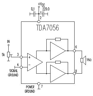
This TDA7056 power audio amplifier circuit diagram project is designed to deliver a maximum output power of 1 watt into an 8-ohm load when powered by a 6-volt supply, or a maximum output power of 3 watts into a...
The Metal-Oxide-Semiconductor Field-Effect Transistor (MOSFET) is analogous to the Junction Field-Effect Transistor (JFET) in several aspects. Both types are voltage-driven unipolar devices that rely on either electron or hole movement, but not both, unlike bipolar transistors. A key structural...
Several schematic drawings of battery charger circuits are provided. These circuits cover 5W to 200W for NiCd, NiMH, Lead-Acid, Li-Ion/Polymer, and LiFePO4 battery packs. The charger circuit files aim to assist users in selecting the appropriate chargers and to...

Transistors Q1 and Q2 are configured as a free-running multivibrator. The output at the emitter of Q2 drives the base of the common emitter amplifier Q3, which controls the lamp. This circuit configuration allows for independent variation of flash...