led noughts and crosses

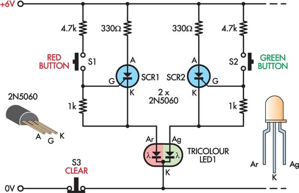
This is a modern twist on the classic game of noughts and crosses, utilizing nine 10mm tri-color LEDs arranged in a 3 x 3 grid. One player has nine red buttons while the other player has nine green buttons, both set up in identical grids. The objective is to align three LEDs in a row to glow the same color, either red or green. When a player presses a red button, the LED in the corresponding position on the grid lights up red. Similarly, pressing a green button activates the equivalent green LED. If a player presses a button for an LED that is already illuminated in red or green, the LED changes to yellow, indicating an invalid move. To reset the game, all LEDs can be turned off by pressing the "Clear" button. For simplicity, the circuit diagram illustrates only one tri-color LED and a pair of opposing buttons, which must be replicated eight more times to complete the 3 x 3 grid. A brief press on a button triggers the associated SCR, activating the LED. The common (cathode) lead of all LEDs connects to the 0V rail through the normally-closed contacts of the "Clear" pushbutton (S3).
The circuit operates by utilizing a grid of nine tri-color LEDs, each capable of displaying red, green, or yellow. The red and green buttons are connected to separate inputs that control each LED's state. When a button is pressed, it sends a signal to a silicon-controlled rectifier (SCR), which allows current to flow to the corresponding LED, illuminating it in the desired color. The design employs a normally-closed contact configuration for the "Clear" button, which ensures that when the button is not pressed, all LEDs are grounded, keeping them off. Upon pressing the "Clear" button, the circuit momentarily opens the connection to the ground, allowing all LEDs to turn off simultaneously.
To implement the complete grid, the circuit design must replicate the LED and button setup for each of the nine positions in the 3 x 3 array. Each LED's cathode connects to a common ground, while the anodes are individually controlled by their respective SCRs. This design allows for immediate feedback in gameplay, as the color change to yellow serves as a visual cue for an invalid move. The simplicity of the circuit, using basic electronic components, ensures ease of construction and reliability in performance, making it an engaging and interactive electronic version of the traditional noughts and crosses game.Here`s a twist to the age-old game of noughts and crosses. Instead of pen and paper, it uses nine 10mm tri-colour LEDs arranged in a 3 x 3 grid. One player has nine red buttons while the other player has nine green, set out in identical grids. The aim, of course, is to make three LEDs in a row glow the same colour red or green! Pushing a red b utton causes the LED in the equivalent position on the grid to glow red in colour. Likewise, pushing a green button lights the equivalent green LED. If a player pushes a button for a LED that is already glowing red or green, then that LED changes to yellow, exposing the false move! All the LEDs are then turned off, ready for the next game, by pressing the "Clear" button. For simplicity, the circuit shows only one tri-colour LED and a pair of opposing buttons. This circuit fragment must be repeated another eight times to create a complete 3 x 3 grid. A brief press on a button fires the associated SCR and turns on the LED. The common (cathode) lead of all LEDs is connected to the 0V rail via the normally-closed contacts of the "Clear" pushbutton (S3).
🔗 External reference


