
15w 12 km range fm transmitter by

The FM transmitter circuit typically consists of several key components, including an oscillator, modulator, and amplifier. The oscillator generates a carrier frequency, which is modulated by the audio input signal. In this circuit, the audio signal is fed into the modulator, where it alters the frequency of the carrier wave according to the amplitude of the input sound.
The coil, or inductor, plays a crucial role in determining the operating frequency of the transmitter. By placing the coil directly on the printed circuit board (PCB), the design enhances stability and reduces interference, allowing for more reliable signal transmission. The PCB layout is essential for minimizing parasitic capacitances and inductances that could affect performance.
The P1 potentiometer serves as a variable resistor, enabling the user to adjust the amplitude of the audio signal before it enters the modulator. This feature allows for fine-tuning of the output signal strength, ensuring optimal transmission quality and preventing distortion.
Power supply considerations are also vital in the design of the FM transmitter. A stable voltage source is required to ensure consistent operation of the oscillator and amplifier stages. Additionally, bypass capacitors may be employed to filter out noise from the power supply, further enhancing the performance of the transmitter.
Overall, this basic FM transmitter circuit is an effective solution for short-range audio transmission, suitable for various applications such as personal broadcasting, educational projects, or hobbyist experiments. Proper attention to component selection, PCB layout, and power supply design will contribute to the successful implementation of this circuit.This is a well designed basic FM transmitter that you can easily recive the signals transmitted from this transmitter in a 1-2km range with using a normal FM reciever. Another property of this circuit is that the bobin is placed on the printed circuit board. The input sound`s amplitude can be adjusted by using the P1 potentiometer. 🔗 External reference
Related Circuits
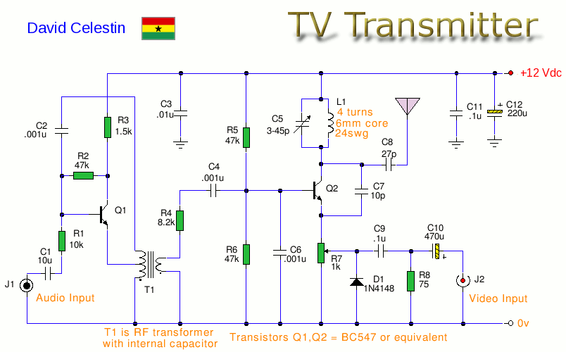
This is an analogue TV transmitter. Sound modulation is FM with a 5.5 MHz carrier, and video transmission uses PAL. The frequency is adjustable via C5 and tunes from 54 to 216 MHz with the components shown. This transmitter...
This FM transmitter circuit is compact, similar to a previous single-chip FM transmitter, but it is monophonic in nature. The circuit can be observed in the provided schematic. This monophonic FM transmitter is designed to operate on a single frequency,...
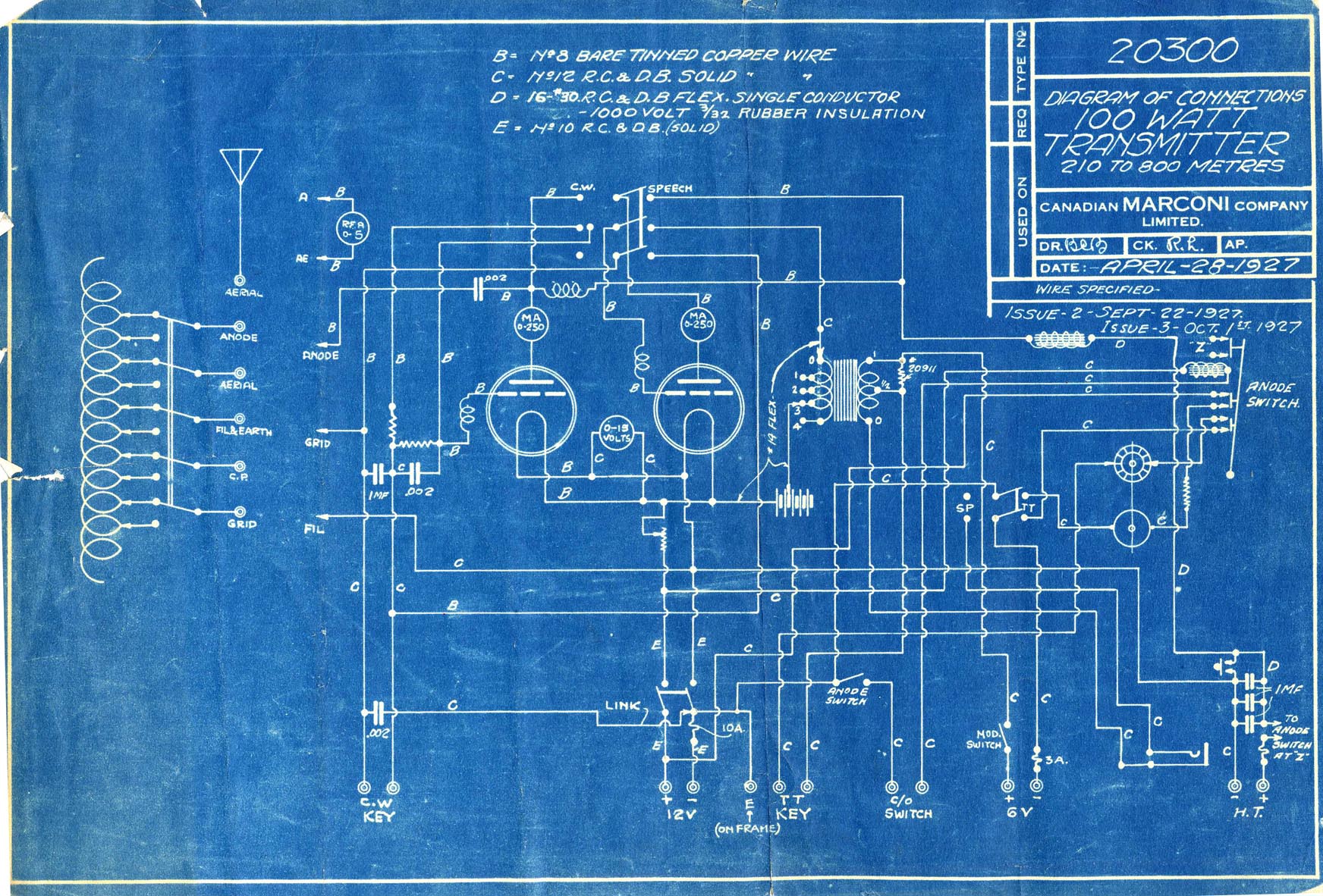
The 100W4 is a two-tube medium frequency transmitter designed for pre-tuning to three frequencies within the medium frequency band, supporting emissions types A1, A2, and A3. In the A1 configuration, both tubes function as parallel oscillators. For A2 and...

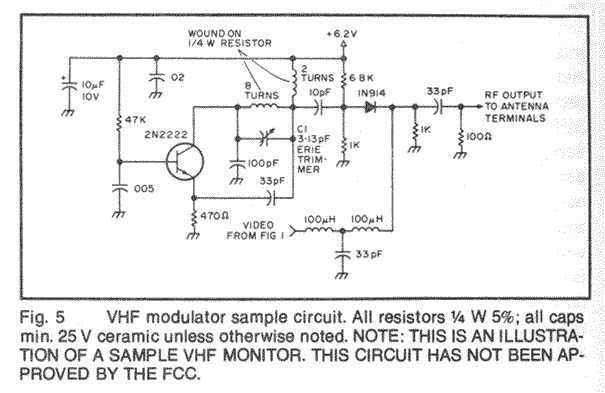
This is a design circuit for a UHF transmitter. The TV transmitter operates within the UHF frequency range of 470-580 MHz, specifically on channels 21-34. It can transmit signals over distances of 30-100 meters using a cable length of...
In this fast-paced world, there is little time for inconveniences and a greater need for portability and adaptability. The idea for an Audio/Video transmitter stems from this need. There may have been times when you’ve wanted to hook up...
This schematic for an experimental data transmitter utilizes optical fibers and a laser diode. The transmission frequency of the free-running oscillator is approximately 3 kHz. Resistor R5 may need to be adjusted to match the specifications of the laser...