
uhf tv transmitter circuit

The UHF transmitter circuit is designed to operate effectively within the specified frequency range, making it suitable for various applications in television broadcasting. The circuit typically consists of several key components, including an oscillator, modulator, amplifier, and antenna.
The oscillator generates the carrier frequency, which is essential for transmitting the signal. It is crucial that the oscillator is precisely tuned to the desired frequency (within the 470-580 MHz range) to ensure optimal performance. The modulator is responsible for encoding the audio and video signals onto the carrier wave, enabling the transmission of television content.
An amplifier is integrated into the circuit to boost the power of the modulated signal before it is transmitted. This amplification is vital for achieving the desired transmission range of 30-100 meters. The choice of components for the amplifier, such as transistors or integrated circuits, will significantly impact the overall efficiency and effectiveness of the transmitter.
The antenna plays a critical role in radiating the transmitted signal into the surrounding environment. The design of the antenna should be matched to the operating frequency to maximize radiation efficiency. A cable length of 10-20 cm is typically used to connect the antenna to the transmitter circuit, which helps in maintaining the proper impedance and minimizing signal loss.
Power supply considerations are also essential for the reliable operation of the UHF transmitter. A voltage range of 9-15 volts is recommended, with the option to use 9V DC batteries for portability. It is important to ensure that the power supply can deliver sufficient current to all components, particularly during peak transmission periods.
Finally, the construction of the coil is a critical element in the design of the UHF transmitter. The coil's dimensions, including the number of turns and the diameter, must be calculated to resonate at the desired frequency. This resonant frequency is determined by the inductance of the coil and the capacitance in the circuit. Proper tuning and adjustments may be necessary to achieve the best performance from the transmitter.
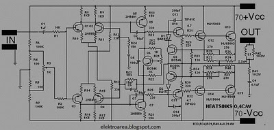
In summary, the UHF transmitter circuit is a sophisticated design that requires careful attention to component selection, tuning, and construction techniques to ensure effective television signal transmission within the specified frequency range.This is design circuit for UHF transmitter circuit. The TV transmitter circuit is working on the UHF channel, 470-580 MHz frequency channel 21-34. This transmitter can radiate as far as 30-100 meters by using a cable 10-20 cm. This is the figure of the circuit. TV transmitter requires supplies voltage of 9-15 Volt. However, you can also use 9v VDC or batteries. This is an important thing to remember for building of the TV transmitter circuit is that the dimensions of coil size to match the frequency of the desired work. The value of the spindle is making coil as follows: 🔗 External reference
Related Circuits
The design of this amplifier aims to enhance the reproduction of complex music and voice. While high electrical properties are emphasized, the primary objective is to achieve superior sound quality, vivid imaging, and exceptional spatial clarity. Although the average...

The circuit depicted here is designed to identify defective bulbs by capacitively sensing the electric fields they generate. To understand its operation, consider a string of bulbs with an open-circuited filament, referred to in the schematic as the String...
This is a circuit design for a PWM speed control circuit for DC motor rotation. The circuit features two functions: Forward-Reverse operation and Regenerative Braking. The control is achieved using a MOSFET. The circuit allows for the control of...
The automotive electronic code lock circuit is depicted above. IC1 is a dedicated lock for the integrated circuit 5G058, with its designated pins connecting an external key switch to the power supply. There are six valid input keys, and...
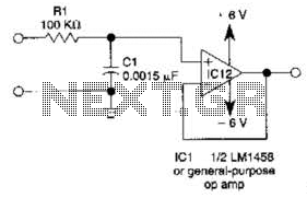
This simple filter utilizes an RC section as the filter element, incorporating a voltage follower to manage other frequencies. The -3 dB point is calculated as 1/(6.28 * RXCV), resulting in a response that drops 6 dB per octave...
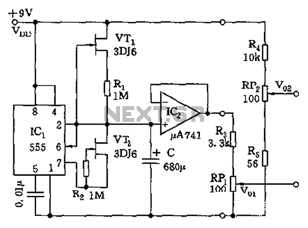
The circuit depicted in the figure is a generator that includes an oscillator, a voltage follower, a zero amplitude adjustment, and a zero shift circuit. It is utilized as a self-balancing recorder for testing signals. The output signal ranges...