
15W - 30W RF Power Amplifier KT922 KT930 KT934

The RF amplifier is a critical component in various communication systems, designed to enhance the strength of radio frequency signals. It operates by taking a weak input signal and increasing its amplitude, thereby making it suitable for further processing or transmission. The performance of the amplifier is influenced by several factors, including the input RF power level, the characteristics of the power supply, and the specific transistor used within the circuit.
In terms of design, the RF amplifier typically includes several key components: the input stage, the amplification stage, and the output stage. The input stage is responsible for receiving the weak RF signal and preparing it for amplification. This may involve impedance matching to ensure maximum power transfer and minimize signal loss. The amplification stage utilizes a transistor, which is the heart of the amplifier, to increase the signal's power. The choice of transistor is crucial, as it affects the amplifier's gain, bandwidth, and overall efficiency.
The output stage of the amplifier is designed to deliver the boosted signal to the next component in the system, which may be an antenna or another stage of processing. It is essential to ensure that the output impedance is matched to the subsequent load to avoid reflections that can degrade performance.
Power supply considerations are also vital, as the amplifier must be adequately powered to achieve the desired performance. The supply voltage and current ratings should match the requirements of the transistor and other circuit components. Additionally, thermal management is important to prevent overheating, which can lead to performance degradation or failure.
Overall, the design and implementation of an RF amplifier require careful consideration of the various parameters to ensure optimal performance in boosting small transmitter signals.This rf amplifier ensure the power you need to boost a small transmitter. Depending of input rf power, power supply and transistor, this amplifier can boos.. 🔗 External reference
Related Circuits
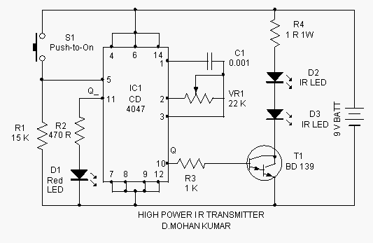
This infrared transmitter is capable of activating IR-based switching circuits from a distance of 10 meters or more. It features a high-power IR transmitter that drives two infrared LEDs. The infrared transmitter circuit is designed for remote activation of devices...
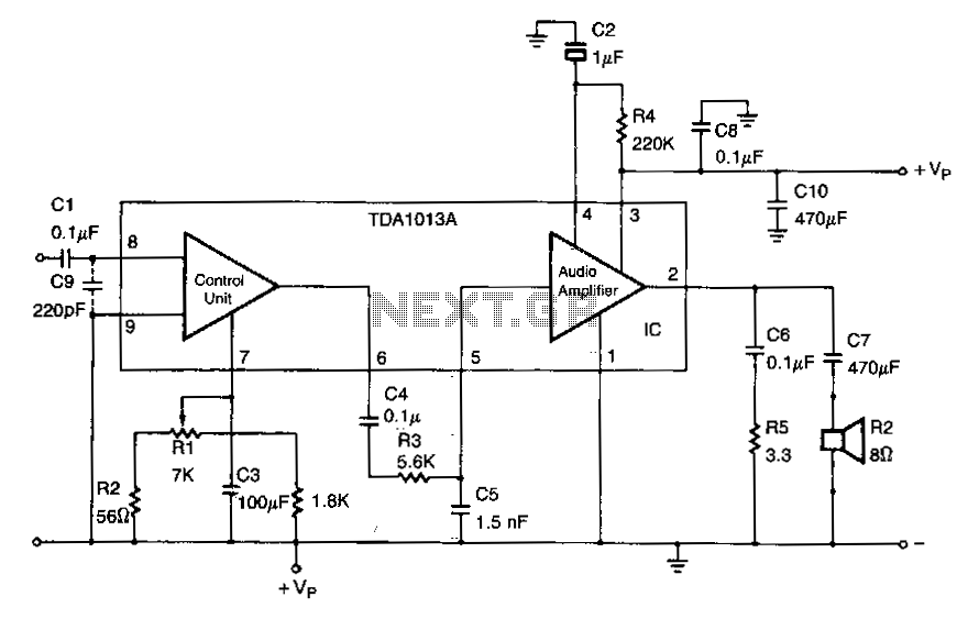
C9 is necessary to filter out RF input interferences. R3 in combination with C5 is used to limit the AF frequency bandwidth. The 470-f.IF power supply decoupling capacitor is C10. C9 serves a critical role in the circuit by acting...
A buffered video amplifier is utilized to connect a video player to a receiver or monitor TV over long cable lengths, which may lead to a reduction in signal amplitude and, consequently, a decline in image quality. This amplifier...
This schematic illustrates an FM, AM/MW, and SW antenna amplifier circuit, also referred to as an antenna preamplifier circuit. It is designed to enhance weak signals from FM, AM/MW, and SW bands. The circuit is straightforward and can be...
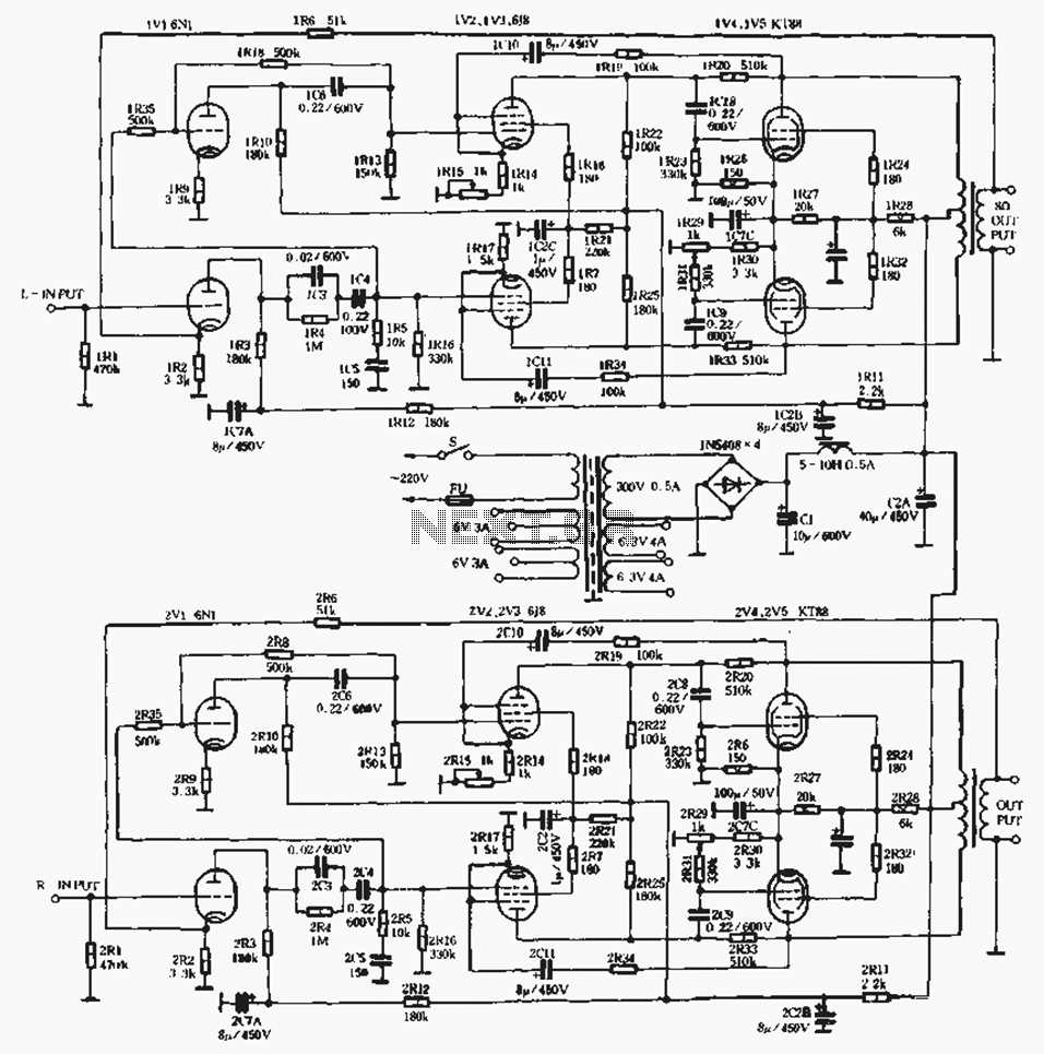
A standard linear amplifier is designed according to a conventional circuit configuration, with the power of the beam tube indicated in Figure 1-8. The output stage employs power tubes such as EL34, KT88, and KT100, which are types of...
This very simple and self-powered device was conceived to allow a person to monitor if someone has rung his home door-bell when he was out. As most door-bells use 12Vac supply, the circuit must be simply connected to the...