
Circuit diagram of grundig 5441 tv

The circuit for the Grundig 5441 television encompasses several key components and functions essential for its operation. The power supply section typically converts mains voltage to the required low voltages needed by various internal circuits. This section may include a transformer, rectifier diodes, and smoothing capacitors to ensure stable DC output.
The main processing unit of the TV is likely based on a microcontroller or a dedicated IC that manages signal processing, user interface, and control functions. Signal input is received through various ports, such as HDMI, composite, or RF, which are routed to a tuner and demodulation circuit for channel selection and processing.
The video and audio signals are then amplified and sent to the output stage, which may consist of a video amplifier and audio amplifier driving the respective display and speakers. Additional components such as feedback loops and filters are included to enhance picture quality and audio fidelity.
The circuit may also incorporate safety features, such as fuses or thermal protection, to prevent damage from overcurrent or overheating. A schematic diagram would typically illustrate the interconnections between these components, showing their arrangement and the flow of signals throughout the circuit.
Overall, the Grundig 5441 TV circuit is designed to provide reliable performance while ensuring user-friendly operation and compliance with safety standards.Circuit for Grundig 5441 tv. If you have any problem regarding this issue come back with more information about the problem, we will glad to assist you By entering the Fixya site you declare that you have read and agreed to its Terms. You may NOT copy or distribute the content that appears on this site without written permission from Fixya
Ltd. © 2005-2014, Fixya, Ltd. or it`s affiliates. 🔗 External reference
Related Circuits
This power supply unit (PSU) has been designed for high-current ham radio transceivers, providing approximately 20 Amps at 13.8V. It features a secondary output capable of handling currents from 15 mA up to a maximum of 20A. The unit...
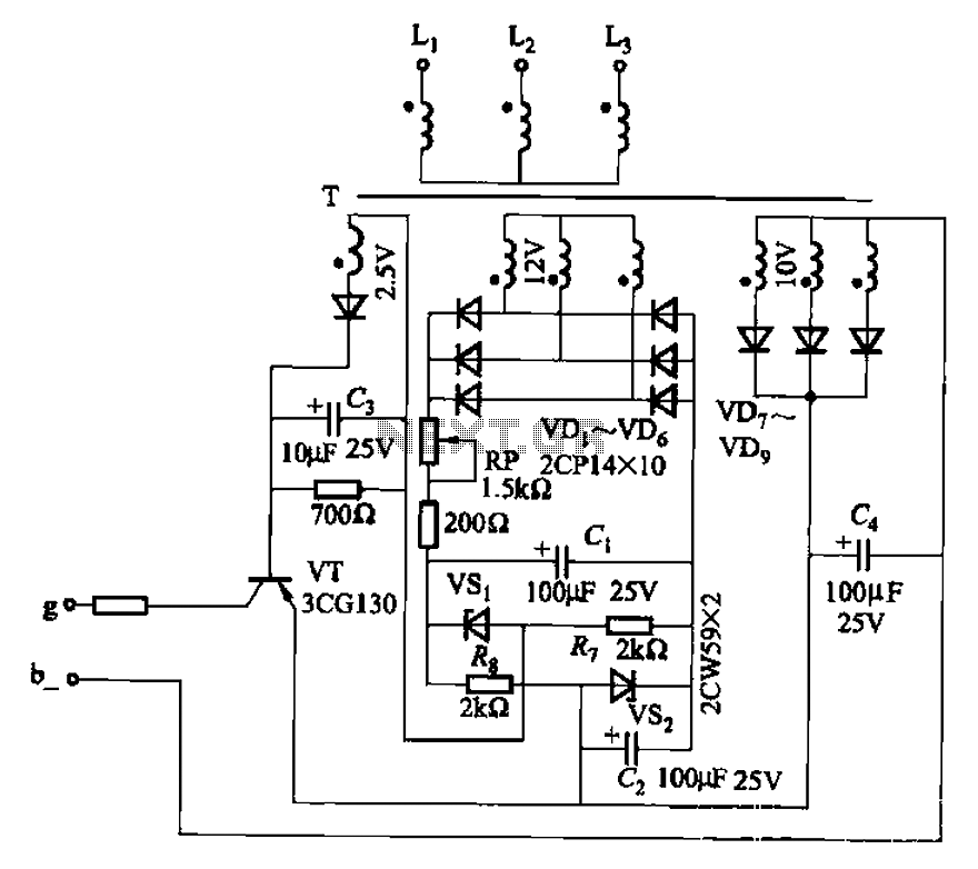
The CJ-12 Excitation Regulator is designed for automatic excitation control of small generators with a capacity of 250 kW or less. Its circuit is illustrated in Figure 7-45. The adjustment potentiometer RP allows for the modification of the measuring...
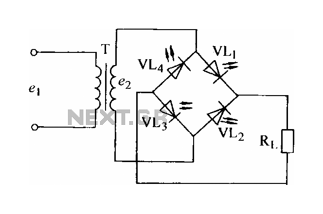
In certain applications, the current from a non-rectified voltage power supply circuit is insufficient. A light-emitting diode (LED) rectifier circuit can be employed to address this issue, serving as a power indicator. It is important to ensure that the...
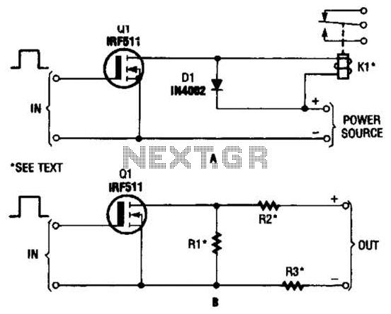
The hexFET can switch DC power to relays, motors, lamps, and various other devices. This configuration can also be utilized to switch resistors in and out of a circuit. R1, R2, and R3 represent resistive loads that can be...
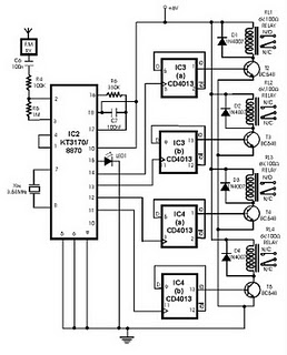
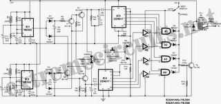
This project utilizes DTMF (dual-tone multi-frequency) signals, commonly used in telephones for dialing digits, as control codes. The DTMF tones are employed for frequency modulation of the carrier signal. At the receiver unit, these frequency-modulated signals are intercepted to...
The following circuit illustrates an Automatic Room Power Control Circuit Diagram. This circuit is based on the NE555 integrated circuit (IC). Features include the use of two Light Dependent Resistors (LDRs). The Automatic Room Power Control Circuit utilizes an NE555...