
1995 ford mustang wiring diagram

No description available.
Related Circuits
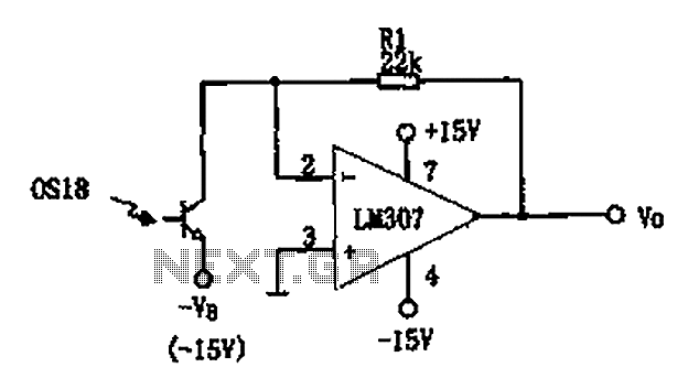
The circuit described is a photoelectric receiver amplifier designed to amplify the electrical signals generated by photodiodes or phototransistors in optoelectronic devices. When the intensity of incident light varies, the photosensitive device generates a corresponding voltage or current. The...
A schematic that illustrates the connections to the Clare IXDI404PI chip, which serves as both the control unit and power driver for a DIY Back-And-Forth robot. The Clare IXDI404PI chip is a dual-channel, high-speed, high-current driver designed for driving inductive...
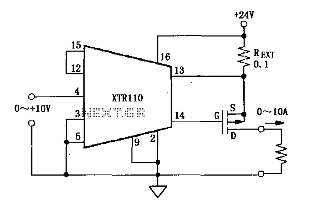
When the output current exceeds 40mA, the XTR110 requires the use of an external resistor (REXT) instead of the internal 50-ohm resistor (R9). REXT should be connected between pin 13 and pin 1. The value of REXT is determined...
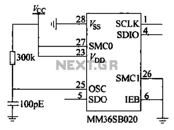
The chip power later, when the strobe IEB is held low, allows for the transfer of memory to the instruction, address, and read or write data. All operations regarding order, address, and data transfer initiate from the least significant...
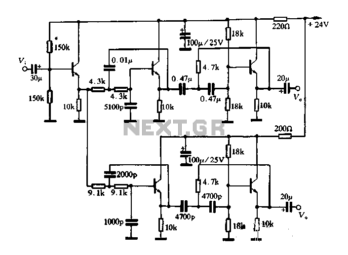
This article describes a band-pass filter circuit diagram utilizing transistors. A band-pass filter is an essential electronic circuit that allows signals within a certain frequency range to pass while attenuating frequencies outside that range. The circuit typically consists of a...
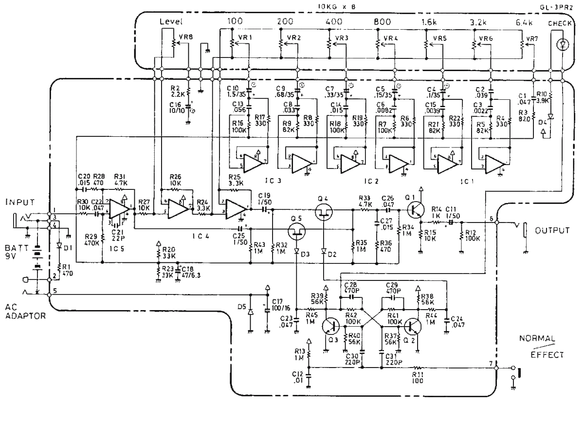
The Boss GE-7 Equalizer pedal modifies the harmonic content of an instrument across 7 distinct frequency bands, spanning from 100Hz to 6.4kHz, with a boost or cut of up to 15dB for each band. An additional Level control knob...