
1Ghz Divide-By-N Counter
The described circuit involves a sophisticated approach to counter design that utilizes dual-modulus prescaling in combination with phase-locked-loop (PLL) synthesizers to achieve high-frequency operation while maintaining low power consumption. The dual-modulus prescaler allows for flexible division ratios, enabling the design to adapt to various applications requiring different frequency outputs.
In this configuration, the programmable counter can be set up to operate in multiple modes (serial, parallel, or data bus), providing versatility in how the counter is integrated into larger systems. The use of low-power devices ensures that the overall system remains energy-efficient, making it suitable for battery-operated or power-sensitive applications.
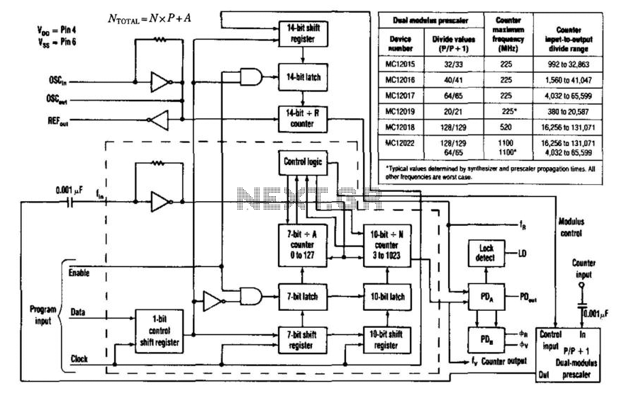
The equation Ntotal = NxP + A is crucial for determining the total division factor, where N represents the programmable division value, P is the modulus of the prescaler, and A is the additional programmable parameter. The choice of the prescaler, which is an 8-pin IC, is essential as it dictates the maximum input frequency and the overall dividing range of the counter.
The output from the counter is made available at the synthesizer pin Fy, which can be interfaced with other components in the system, such as frequency synthesizers or digital signal processors. The design ensures that the counter can handle high-frequency signals while providing a reliable output that meets the specifications of modern electronic systems.
In summary, this circuit design exemplifies the integration of advanced digital techniques to enhance the performance of counters, making it a valuable solution in high-speed and low-power applications. Counter speeds for CMOS- and TTL-programmable counters are limited to under 100 MHz. ECL-type devices can approach a few hundred MHz, but with significant current requirements. However, coupling the dual-modulus-prescaling technique with the available phase-locked-loop synthesizer chips that control the prescaler circumvents these frequency and power-drain constraints. With this approach, designers can also choose various counter-programming schemes (serial, parallel, or data bus), in addition to achieving higher frequency capabilities.
Low-power drain (less than 75 mW) and low-cost devices can also be selected. Moreover, only two ICs are necessary to achieve divide values above 131000. Maximum input frequency and dividing range for the counter are controlled by choosing an appropriate 8-pin dual-modulus prescaler. The counter"s output appears at synthesizer pin Fy (see the figure). The total input-to-output divide value is governed by the equation: Ntotal = NxP+A and A represent the value programmed through the serial port into the divide-by-jV and divide-by-A counters.
is the lower dual-modulus value that is established by the synthesizer"s modulus-control signal. Typically, A varies from zero to P-l to achieve steps within the system"s divide range. must be equal to or greater than A. N>A then sets a lower limit on NT0tal> which is dictated by Amax = P- 1. 🔗 External reference
Related Circuits
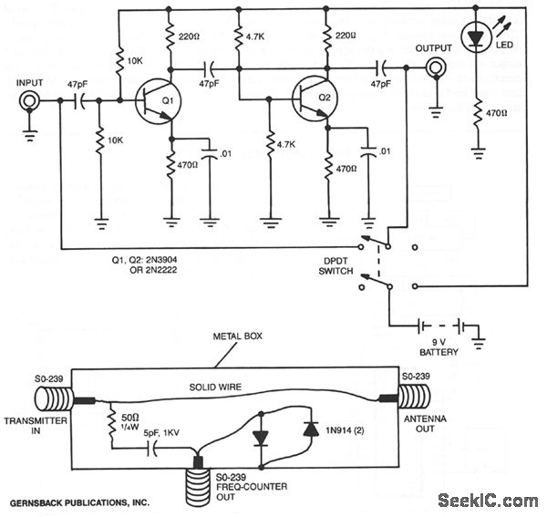
By utilizing a preamplifier with a short length of shielded cable and clip leads, signals that typically do not produce a readout can generate precise and stable readouts on the counter. A DPDT switch is incorporated to bypass the...
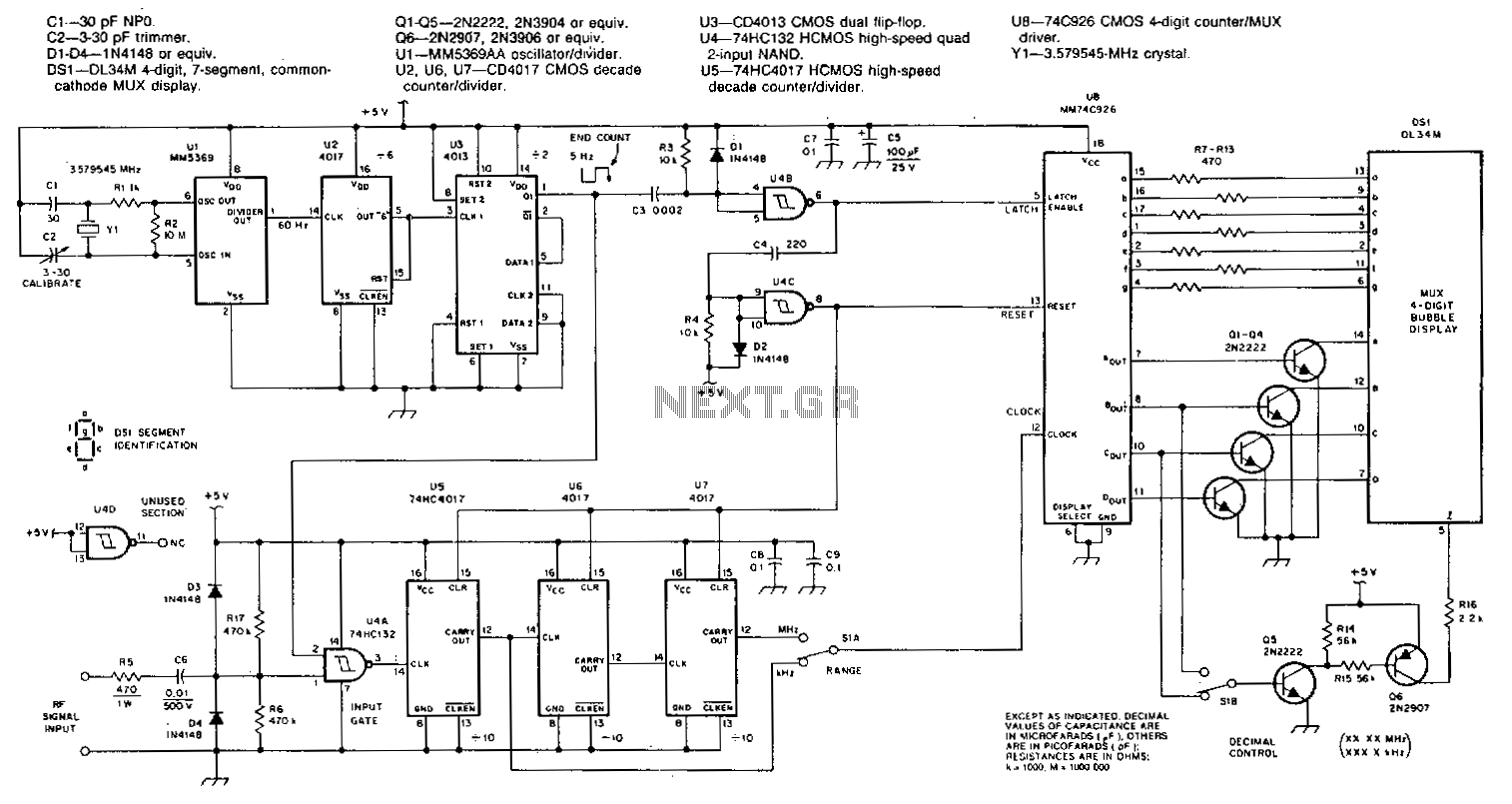
This counter utilizes a four-digit display, which can show frequencies ranging from 1 to 40 MHz when the range switch is activated, achieving a resolution of 100 Hz. The MM74C926 CMOS integrated circuit features a four-digit decimal counter that...
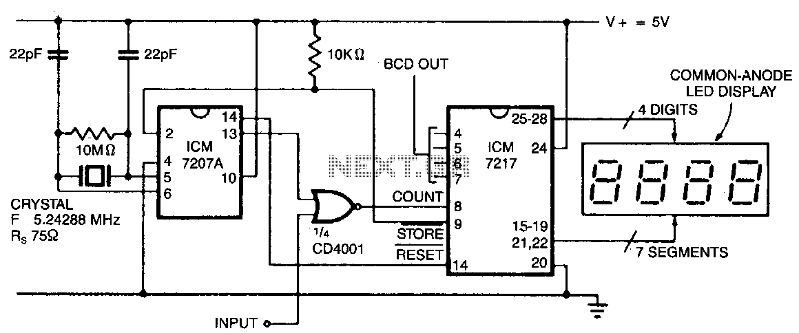
In this configuration, the display shows hertz directly. When pin 11 of the ICM7027 A is connected to V00, the gating time is set to 0.1 seconds, allowing the display to represent tens of hertz as the least significant...
At the initial state, all pin 15 connections are grounded, causing resistor R0 to be energized. A 555 multivibrator generates a clock signal to IC1, activating the outputs from R0 to R8. This basic circuit can be employed to...
The working principle involves two pairs of photoelectric detection devices installed in the access channel. One side features light source A (transmitter) and photoresistor LDR1 (receiver) at the entrance of the channel, while the other side contains light source...
A wide range frequency meter is a useful tool for an electronics lab. This project describes a frequency meter based on the AT90S231 microcontroller that can measure input frequencies up to 50 MHz. The measured frequency is displayed on...