
1W FM Transmitter

The 1-watt FM transmitter circuit is designed for efficient signal transmission with minimal distortion. The first transistor functions as a high-frequency oscillator, generating the carrier wave at the desired frequency. The stability of this oscillator is crucial for maintaining a consistent frequency output, which is achieved through careful component selection and circuit design.
Following the oscillator, the buffer stage is implemented using a second transistor. This stage isolates the oscillator from the load and ensures that any adjustments made to the transmitter do not affect the frequency stability. The buffer stage also amplifies the signal strength, preparing it for further processing.
The resonance stage is critical for tuning the transmitter to the desired frequency. It typically consists of an LC circuit (inductor-capacitor) that allows for fine-tuning of the output frequency. The quality of the components used in this stage will directly impact the transmitter's performance and range.
The final stage of the circuit employs a high-power transistor capable of delivering at least 1 watt of output power. This transistor must be adequately cooled, necessitating the use of a heatsink to dissipate heat generated during operation. Proper thermal management is essential to prevent overheating and ensure reliable performance over extended periods.
Powering the circuit requires stable voltage supplies. The LM7805 voltage regulator is employed to provide a constant 5V supply for the oscillator diodes, ensuring that they operate within their specified voltage range. The LM7809 regulator supplies 9V to the T1 oscillator stage, which is necessary for optimal operation of the transmitter.
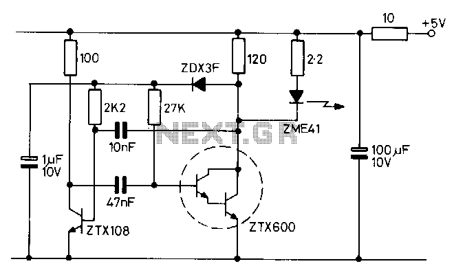
Overall, this 1-watt FM transmitter circuit is an excellent choice for hobbyists and professionals alike, offering a balance of simplicity and performance. By following the schematic carefully and using quality components, users can achieve a reliable and stable FM transmission system suitable for various applications.A very good 1 watt fm transmitter circuit, very easy to build circuit. It has 4 transistors, one is a very stable oscillator, followed by a buffer stage to prevent frequency variation when you adjust the transmitter. Next is a resonance stage and the final stage built with a minimum 1W transistor which must have a heatsink.
You must use a LM7805 stabilizer for the oscillator diodes and one LM7809 for powering up the T1 oscillator stage. This will give you a very stable transmitter frequency 🔗 External reference
Related Circuits
This is a well-designed basic FM transmitter that allows the reception of transmitted signals within a range of 1-2 km using a standard FM receiver. Additionally, the circuit features a coil mounted on the printed circuit board. The amplitude...
This 2-meter 144 MHz fox hunt transmitter is utilized in amateur competitions where a concealed transmitter is to be "hunted" using primarily homemade receivers. The 2-meter 144 MHz fox hunt transmitter is designed for use in amateur radio competitions, commonly...
This is a small but quite powerful FM transmitter having three RF stages incorporating an audio preamplifier for better modulation. It has an output power of 4 Watts and works off 12-18 VDC which makes it easily portable. It...
The transmitter consists of an oscillator that drives a high-output infrared (IR) emitting diode. The oscillator is a simple multivibrator circuit that provides an output with a mark-to-space ratio ranging from 15 to 1000 at a frequency of 1...
Integrated circuits (ICs) that were once prohibitively expensive for hobbyists are now more affordably priced. A notable example is the AD8099 from Analog Devices, which is available for a modest cost. The AD8099 is a high-speed operational amplifier (op-amp)...
Crystal 80mW FM transmitter circuit diagram of the production The Crystal 80mW FM transmitter circuit is designed to generate frequency modulated (FM) signals suitable for short-range audio transmission. This circuit primarily consists of a crystal oscillator, which serves as...