
Car lamp charger

The Car Lamp Charger circuit is designed to provide a reliable power source for automotive lighting, integrating a straightforward approach to battery management. The circuit's architecture can be divided into several key components, including the power supply section, the charging mechanism, and the load management system.
In the power supply section, the circuit can be powered by six 1.5V batteries connected in series, providing a total voltage of 9V, or by using an external power source with an appropriate output current rating. This flexibility allows the circuit to adapt to various power sources, making it versatile for different applications.
The charging mechanism of the NiCd battery charger is particularly notable for its simplicity and efficiency. It features current and voltage limiting capabilities to ensure safe charging of the NiCd batteries. The use of LEDs for current regulation is an innovative approach that allows for real-time monitoring of the charging process. When the NiCd battery is low, lamp L1 lights up, indicating that charging is in progress, while the LED turns off, signaling that the battery is receiving sufficient current.
Furthermore, the integration of a miniature 3-volt solar battery enhances the circuit's functionality, allowing it to harness solar energy for charging. This feature is especially beneficial for portable applications, as it enables the device to charge various electronic gadgets, including cellular phones. The conversion of solar energy into a pulsed current for charging is achieved through a simple yet effective circuit design, ensuring that the charging process is efficient and reliable.
Overall, the Car Lamp Charger circuit exemplifies a well-thought-out design that combines functionality, efficiency, and versatility, making it suitable for a wide range of applications in automotive and portable device charging.The schematic diagram come from circuit: Car Lamp Charger power supply. Go to that page to read the explanation about above power supply related circuit diagram. Scheme of the Car lamp charger is shown in above. A distinctive feature of the scheme is that the battery will never recharge. This Car lamp charger circuit is built into the "Chinese" la ntern, which originally had 4 batteries. Setting. This simple converter to power UV lamp scheme is a simple converter to power the ultraviolet lamp low voltage. The power supply can be applied using the 6 batteries of 1. 5V or a power supply with an output current of. This NiCd battery charger circuit is very simple but it has a current and voltage limiting. Lamp L1 will light brightly and the LED will be out when the nicd battery is low and being charged, but the LED will.
This Nicd charger circuit diagram is another simple NiCd battery charger, and I think its very interesting because uses LEDs to adjust the charging current. As mentioned above, this Nicd charger circuit uses constant current LEDs to adjust charging current. . To charge the 6-volt NiCd battery in this little device uses a miniature 3-volt solar battery. Battery, in turn, can charge many models of cellular phones and other portable devices. The circuit converts solar energy into a pulse current charging. We aim to transmit more information by carrying articles. Please send us an E-mail to wanghuali@hqew. net within 15 days if we are involved in the problems of article content, copyright or other problems.
We will delete it soon. 🔗 External reference
Related Circuits
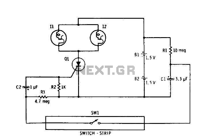
Capacitor C1 is connected continuously through a supply of 3 volts to a 10 megohm resistor R1. The capacitor charges relatively slowly to 3 volts. When switch SW1 is closed, it connects the charged capacitor C1 in series with...

This is an automatic battery charger circuit that utilizes the LM324 integrated circuit, which enhances efficiency. It is capable of charging both 12V and 6V batteries, with filtration managed by switch S1. The circuit is designed to stop charging...
A varying brightness AC lamp circuit utilizes a silicon-controlled rectifier (SCR) to gradually adjust the intensity of a 120-volt light bulb by controlling the duration of AC line voltage applied to the lamp during each half cycle. The circuit...
This simple circuit makes it possible to monitor the charging process to a higher level. If you need more information then check out the LM3914 Datasheet. Final adjustments are simple and the only thing needed is a digital voltmeter...
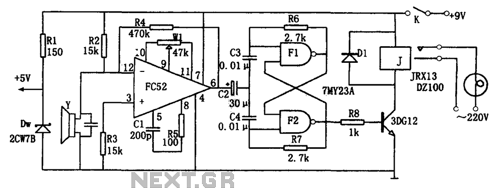
The voice-activated lamp circuit consists of an operational amplifier FC52, a flip-flop made from two NAND gates TMY23A, a relay J, a piezoelectric crystal speaker Y, and additional components. The flip-flop processes the sound signal from the speaker, converting...
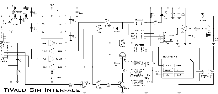
The electronic adapter derives its power supply from the VCC line of the smartcard reader device, or alternatively, an external 5 V supply can be utilized. The RST line of the card slot is connected to one of the...