
Lithium battery indicator

The circuit for the state-of-charge indicator typically employs a voltage comparator to monitor the voltage levels of a battery pack, specifically a 4-cell arrangement. The voltage range of 9.6 to 5.2 volts corresponds to the nominal fully charged state and the cut-off voltage for the cells. The voltage comparator is configured to compare the voltage from the battery cells against a reference voltage, which is set to indicate specific charge levels.
In this configuration, the battery voltage is fed into the non-inverting input of the comparator, while the reference voltage is connected to the inverting input. As the battery discharges, its voltage decreases, and when it falls below the reference voltage, the output of the comparator changes state, triggering an LED or another visual indicator. This provides a clear visual representation of the state of charge.
The circuit can be designed with hysteresis to prevent rapid toggling of the output due to noise or small fluctuations in the battery voltage. Additionally, resistors and capacitors may be included to fine-tune the response time and stability of the circuit. The choice of components, such as the comparator IC and the visual indicator, should be made based on the intended application and the desired sensitivity and accuracy of the state-of-charge indication.
Overall, this voltage comparator circuit serves as an effective solution for monitoring the state of charge in battery management systems, particularly for applications involving multiple cells in series.State-of-Charge indication of-a sloping-voltage discharge can be used as a state-of-charge indicator. A typical voltage comparator circuit that gives a visual indication of state-of-charge is shown. Components identified are for a 4-cell input voltage of 9.6 to 5.2 volts.
Related Circuits
This device is a successor to the PIC16C71 4-digit LED frequency counter and voltmeter. It omits some hard-to-find components from the previous version that have been out of production for some time. The earlier PIC16C71 has been replaced with...
This automatic NiCd charger for 9V NiCd batteries utilizes the properties of a 555 timer and is straightforward to construct. The design allows for continuous charging of the battery without the risk of overcharging or discharging. With the specified...
Schematic and description of a simple and easy-to-build NiCd and NiMH battery charger circuit that is capable of charging multiple NiCd and NiMH batteries. The circuit for the NiCd and NiMH battery charger is designed to be straightforward, allowing for...
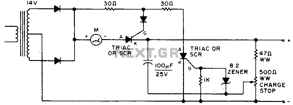
Adjust by setting the 500-ohm resistor while attached to a fully charged battery. The circuit involves a 500-ohm resistor that is to be adjusted while it remains connected to a fully charged battery. This setup is typically used in applications...
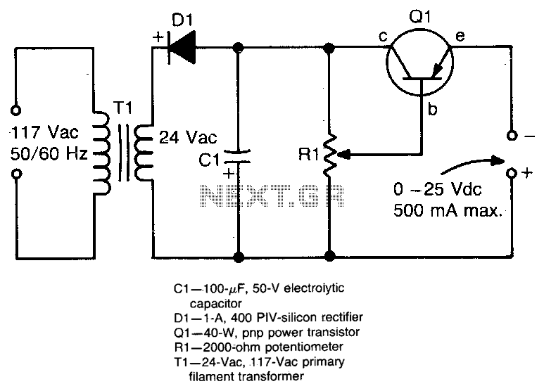
This circuit provides an adjustable output voltage of up to 35 V DC with a maximum output current of 50 mA. The transistor Q1 dissipates significant heat and must be mounted on a heatsink. The circuit in question is designed...
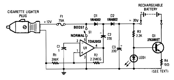
V1 creates a square wave oscillator, while D1 and D2 couple this square wave to a 12-V battery, raising the voltage to over 20 VDC. If this elevated voltage is not required, S1 can remain open. Q1 functions as...