
Fans of natural wind simulator circuit 2
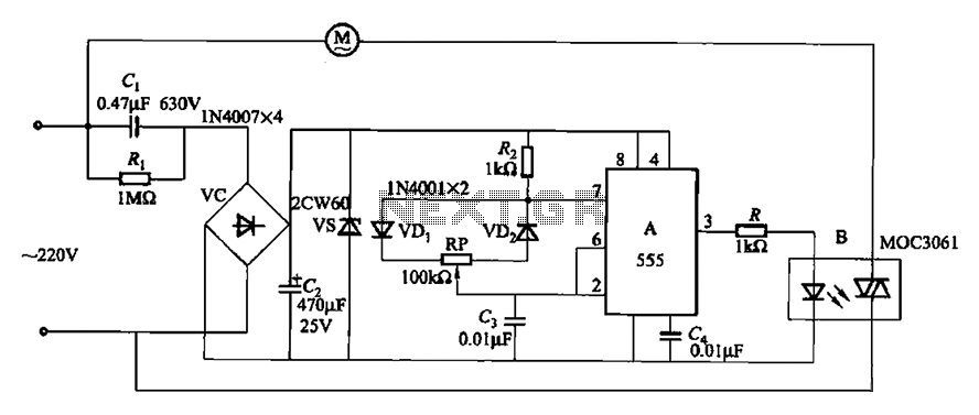
The circuit utilizes the MOC3061, a phototransistor optoisolator, which serves as an interface between the control signal and the fan operation system. The MOC3061 is designed to provide electrical isolation, ensuring that the control circuit does not interfere with the fan's power circuit. This is particularly important in applications where the fan operates at high voltages or currents, as it protects sensitive components in the control circuit from potential damage.
In this configuration, the input side of the MOC3061 is connected to a control signal, which could be generated by a microcontroller or a manual switch. When the control signal is activated, the internal LED of the MOC3061 emits light, which is detected by the phototransistor on the output side. This triggers the phototransistor to conduct, allowing current to flow through the fan's circuit, thus turning the fan on.
The zero-off feature indicates that the circuit is designed to maintain the fan operation at zero voltage, enhancing energy efficiency and reducing unnecessary power consumption when the fan is not needed. The use of a zero-crossing detection mechanism ensures that the fan is activated at the optimal point in the AC waveform, minimizing electrical noise and potential interference with other devices.
Overall, the circuit design emphasizes safety, efficiency, and reliable operation, making it suitable for various applications where fan control is required. The integration of the MOC3061 allows for seamless control while maintaining electrical isolation between the control and power circuits. Circuit shown in Figure 3-9. It is similar to Figure 3-8, except that zero off MOC3061 type photoelectric coupling B directly connected to control fan operation.
Related Circuits
The Bong circuit is a high-frequency Colpitts oscillator that utilizes a Ge coil (L). It features two heads and is designed for simple production. The frequency of oscillation can be determined, and testing is conducted to ascertain the value...

This is a circuit design for a doorbell that produces a bird-like sound. The circuit is controlled by an NPN transistor. The operation of the circuit begins when P1 is set to an experimental value, starting with approximately 220...
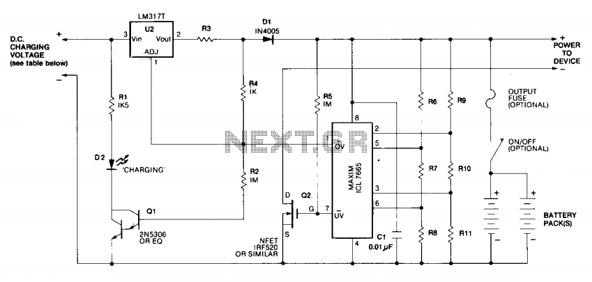
Charging is achieved using a constant current of 60 mA for AA cells, reaching a cutoff voltage of 2.4 V per cell, at which point the charging process must be terminated. The charging system is designed for multi-cell battery...
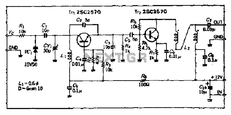
Field strength meters are essential tools for individuals working with radio transmitter electronics. The following is an example of a circuit that serves this purpose. A field strength meter circuit typically consists of several key components, including an antenna, a RF...
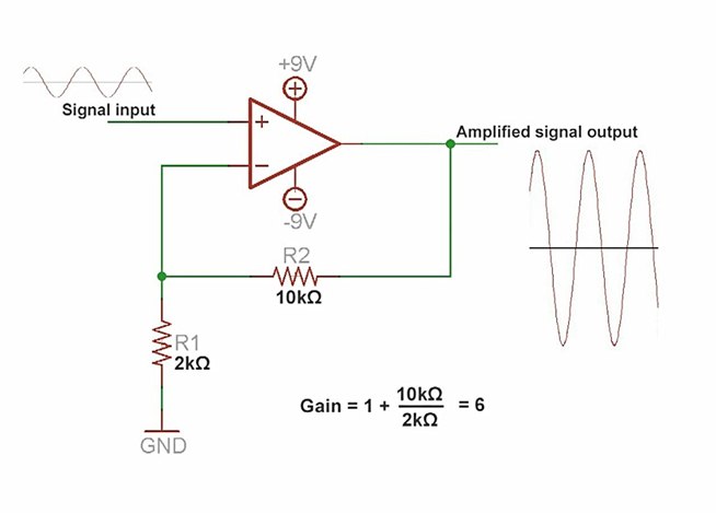
An amplifier is a device that increases the voltage in a circuit. The simplest type is an operational amplifier, and this video will demonstrate how these devices function and how to implement them in electronic applications. As an example,...
This circuit utilizes a relay to control a water pump, enabling automatic level management of a water reservoir or well. The shorter steel rod functions as the "water high" sensor, while the longer rod serves as the "water low"...
Warning: include(partials/cookie-banner.php): Failed to open stream: Permission denied in /var/www/html/nextgr/view-circuit.php on line 713
Warning: include(): Failed opening 'partials/cookie-banner.php' for inclusion (include_path='.:/usr/share/php') in /var/www/html/nextgr/view-circuit.php on line 713