
2 Input Pulses Frequency Comparator

The described circuit implements a frequency comparator using a combination of digital and analog components to evaluate and compare the frequencies of two input signals. The core of the system is formed by two D-type flip-flops (74HCT74), which are configured to capture the leading edges of the incoming pulse trains, F1 and F2. The outputs of these flip-flops, denoted as Q1 and Q2, are then fed into a NAND gate (74HCT00). The NAND gate serves as a logic element that resets the flip-flops when its output is low, indicating that the frequencies of the two signals are equal or that F2 has a higher frequency than F1.
In the operation of the circuit, if F1 has a higher frequency than F2, Q1 will produce a continuous pulse train while Q2 will exhibit a needle-like output. This behavior indicates that the energy content of Q1 is greater than that of Q2, which can be utilized for further processing or signaling.
To ensure that the signals are clean and free from high-frequency noise, Q1 and Q2 are passed through a low-pass filter, which is composed of resistors R1, R2 and capacitor C1. This filtering stage smooths the pulse trains, allowing for a more accurate comparison of their average levels.
The filtered signals are subsequently fed into an analog comparator circuit (LM311), which compares the amplitudes of Q1 and Q2. The output of the LM311 can drive an LED, providing a visual indication of the comparison result. Additionally, this output can be utilized as a digital signal, allowing for integration with other digital logic circuits or microcontrollers for further processing or control applications.
This frequency comparator circuit is valuable in various applications such as frequency measurement, signal integrity testing, and in systems where frequency monitoring is critical for performance optimization.This circuit uses a 74HCT74, 74HCT00, and a LM311 to form a frequency comparator. The two pulse trains are fed to two D-type flip-flops (triggered by the leading edges). The flip-flops' outputs are compared in a NAND gate. If the output of the NAND gate becomes "0", the flip-flops are reset. If the frequency of F1 is higher than the frequency of F2, the signal "Q2" consists of needles and "Q1" is a pulse train. Therefore, the energy content of Q1 is higher than that of Q2. Q1 and Q2 come via a low-pass filter (consisting of R1, R2 and C1) and are compared by an analog comparator circuit (IC3). The comparator drives an LED and can act as a digital output. For the 🔗 External reference
Related Circuits
The CAMD CM8870 CM8870C offers complete DTMF receiver functionality by combining both the band-split filter and digital decoder capabilities into a single 18-pin DIP, SOIC, or 20-pin PLCC package. The CM8870C is produced using advanced CMOS process technology, ensuring...
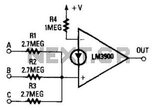
This circuit produces a high output only when all three inputs are high. The current at the non-inverting input must exceed that of the inverting input when all three inputs are high, as determined by resistor R4. The circuit...
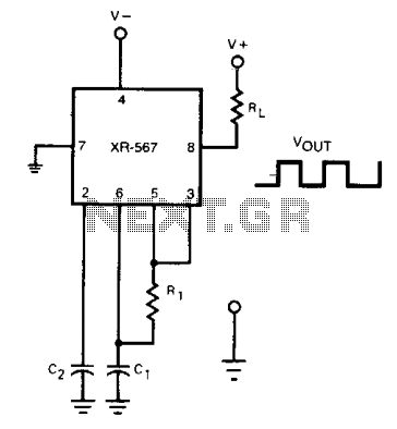
The frequency of the current-controlled oscillator can be doubled by feeding a portion of the square-wave output from pin 5 back to the input at pin 3. This configuration allows the quadrature detector to operate as a frequency doubler,...
The two circuits demonstrate the generation of low-frequency sine waves by shifting the phase of the signal through an RC network, facilitating oscillation when the total phase shift reaches 360 degrees. The transistor circuit on the right produces a...
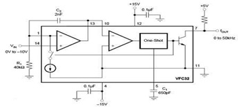
The circuit diagram of a voltage-to-frequency (V/F) converter is presented, designed to handle negative input voltage. It employs the VFC32 voltage-to-frequency converter, which is commonly utilized in various applications. The V/F converter circuit is essential in converting an analog voltage...
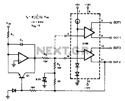
The D169 functions as a level detector, offering complementary outputs. An operational amplifier (op amp) is employed to integrate the input signal Vin, utilizing a time constant defined by the resistor R1 and capacitor C1. A negative input signal...