
2 LED Flasher

The described circuit utilizes an analog flip-flop configuration to achieve a dual LED flashing effect. The primary components include two light-emitting diodes (LEDs), a power supply, and resistors that influence the flashing frequency. The circuit is designed to operate with a 12V power supply, making it suitable for various applications where a higher voltage is available.
For the LEDs, the circuit is optimized for blue or white 3V types. When using these LEDs, the circuit includes 1K ohm resistors to limit the current and ensure safe operation. If alternative LED colors such as red, green, or yellow are employed, the resistors should be increased to 2.2K ohms. This adjustment compensates for the different forward voltage drops associated with these colors, providing the necessary current regulation.
The flashing interval of approximately 1 second is a result of the timing components in the flip-flop circuit, specifically the 100K ohm resistors. Altering these resistors will modify the charge and discharge time of the timing capacitor, thereby adjusting the flashing speed of the LEDs. Decreasing the resistance will lead to a faster flashing rate, while increasing it will result in a slower flashing rate.
Overall, this circuit is an effective demonstration of basic flip-flop operation and LED control, suitable for educational purposes or practical applications requiring visual indicators. Proper attention to component values and LED types will ensure reliable performance throughout its operational lifespan.This is a 2 LED flashing circuit. It is based on an analog flip flop circuit. This particular circuit was calculated to use blue or white 3V LED with a 12V power supply. If you are using red green or yellow LED, replace the 1K resistors for a 2.2K. This circuit will flash the led at a 1 sec interval in alternance. For faster or slower flashing speed, you can increase or decrease the 100K resistors. 🔗 External reference
Related Circuits
The circuit presented this month is a basic configuration of the very versatile 4017 IC Chip. In the most common use of the IC, it will turn on 10 separate outputs sequentially. Typically, the circuit is used to turn...
This Project is made up with AT89C2051 and the RTC DS1307. It has a large Seven segment display. The standard remote control is used to change the Time. More: Procedure to enter the Time 1. Press power button on...
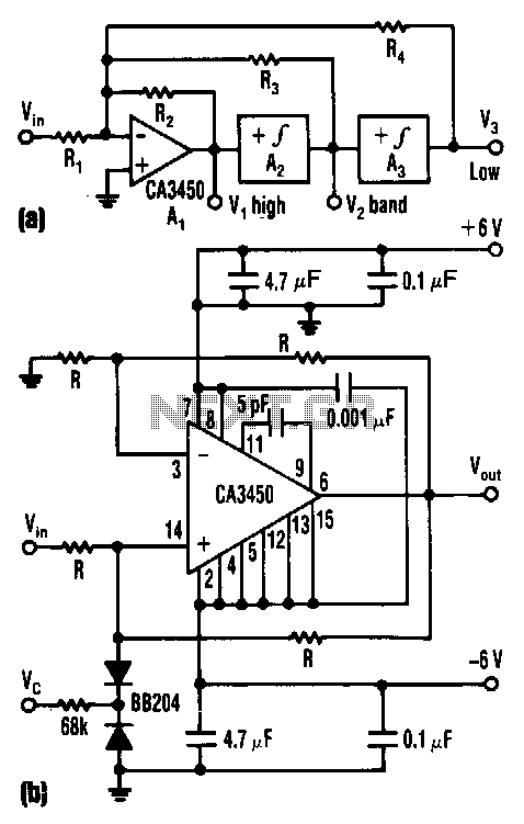
The control voltage Vc effectively adjusts the cutoff frequency w0 of this state-variable filter to any desired value, ranging from approximately 1.7 MHz to 5 MHz, using a BB 204 varicap and a resistance of 100 kΩ. Vc can...
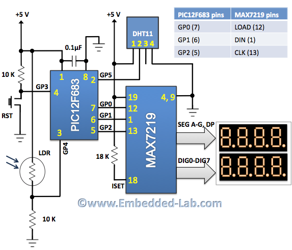
An automatic brightness adjustment is a closed-loop system that has the capability to assess ambient light and adjust the brightness of the display accordingly. The automatic brightness adjustment circuit operates by utilizing a light sensor, typically a photoresistor (LDR) or...
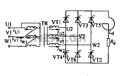
Trigger circuit routing forms include various types such as simple trigger circuits, single-junction transistor trigger circuits, synchronous sine wave trigger circuits, sawtooth transition phase shift (synchronous) trigger circuits, and integrated trigger circuits. This section presents individual cases for introduction...
Five pins RA0 to RA4 are used as inputs. The pins are connected to the 5V average resistance 10K (Pull-up). So when no switch is not depressed all the pins have a high potential (HI +5 V). When one...