
Implementing Adaptive Brightness Control to Seven Segment LED Displays

The automatic brightness adjustment circuit operates by utilizing a light sensor, typically a photoresistor (LDR) or photodiode, to detect the level of ambient light in the environment. The sensor generates a voltage signal proportional to the intensity of the light. This signal is fed into a microcontroller or an operational amplifier configured as a comparator.
The microcontroller processes the input from the light sensor and compares it to predefined threshold levels. Based on this comparison, the microcontroller generates a control signal that adjusts the brightness of the display. This is typically achieved through a pulse-width modulation (PWM) technique, which varies the duty cycle of the voltage supplied to the display backlight, allowing for smooth transitions in brightness levels.
The circuit may also include additional components such as resistors to form a voltage divider with the light sensor, capacitors for filtering noise, and possibly a transistor or MOSFET to handle the power requirements of the display backlight. The design ensures that the display remains easily readable in varying lighting conditions, enhancing user experience and reducing eye strain.
To further enhance the system, a feedback loop can be implemented where the actual brightness level of the display is monitored and compared to the desired level, allowing for real-time adjustments. This closed-loop feedback mechanism ensures optimal performance and responsiveness to changes in ambient lighting conditions.An automatic brightness adjustment is a closed loop system that has the capability to assess ambient light and adjust the brightness of the display accordingly. In .. 🔗 External reference
Related Circuits

The LED meter circuit is more compact and simpler than its analog equivalent, making it a common choice in audio equipment. This circuit utilizes the LM3915 integrated circuit (IC) and operates in a logarithmic mode. It comprises a single...
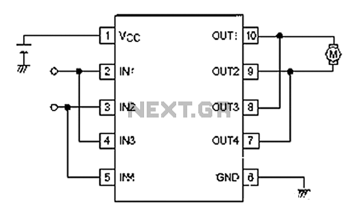
A simple motor control project for forward and backward drive can be implemented using the LB1948M motor driver IC, which features two channels for motor control. The LB1948M is an ideal choice for 12V motor drive systems and can...
The wireless light switch circuit described here requires no physical contact for operating the appliance. You just need to move your hand between the infrared LED (IR LED1) and the phototransistor (T1). The infrared rays transmitted by IR LED1...
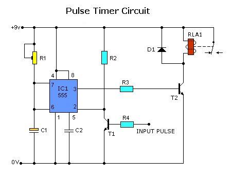
Today, solutions are offered for a timed control relay that utilizes Normally Open (NO) and Normally Closed (NC) contacts to manage the operation of other devices, enabling or disabling them as needed. The functionality of this circuit is based...
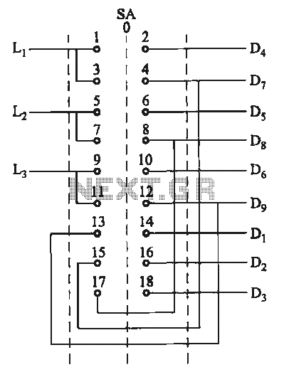
The motor switch control circuit depicted in the figure provides two speed settings for counter-steering, allowing for operation at two speeds in opposite directions. The motor switch control circuit is designed to facilitate the operation of a motor at two...
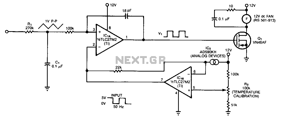
The controller circuit is designed to reduce a fan's noise, power consumption, and wear, especially when operating in low, fluctuating ambient temperatures. A temperature sensor is mounted in the fan's airstream, allowing the circuit to adjust the fan speed...