
A Phase Controlled Triac (HT-32)
")
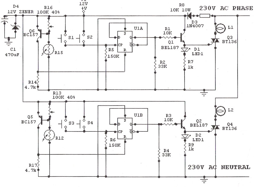
The Phase Controlled Triac circuit, utilizing the HT-32 component, is designed for applications requiring precise control of AC power. The circuit primarily consists of a Triac, which is a semiconductor device that can control the power flow in AC circuits by switching on and off at specific points in the AC waveform. The phase control method allows for the adjustment of the output voltage by delaying the triggering of the Triac.
In this circuit, bilateral trigger diacs are employed to ensure that the Triac can be activated in both halves of the AC cycle. This feature is particularly advantageous as it allows for symmetrical control of the load, regardless of the AC waveform's polarity. The simplicity of the circuit design facilitates easy implementation and troubleshooting, making it suitable for various applications, such as light dimmers, motor speed controls, and heater controls.
The circuit operates by utilizing a phase control technique, where the firing angle of the Triac is adjusted by varying the resistance and capacitance in the triggering circuit. The diacs serve as a trigger mechanism, allowing the Triac to turn on when the voltage across them exceeds a certain threshold. This ensures that the Triac remains off until the desired phase angle is reached, providing smooth control over the power delivered to the load.
Overall, the HT-32 Phase Controlled Triac circuit represents an efficient and effective solution for managing AC power in a variety of electronic applications, emphasizing ease of use and reliability.The following circuit shows about A Phase Controlled Triac (HT-32) Circuit Diagram. Features: Dsimple circuit, bilateral trigger diacs offers a .. 🔗 External reference
Related Circuits
Light Sensitive Staircase Switch with Triac. The operation of the third circuit is similar, except that it incorporates photo sensitivity. The circuit is illustrated in the schematic. When there is insufficient light... A light-sensitive staircase switch utilizing a TRIAC is...
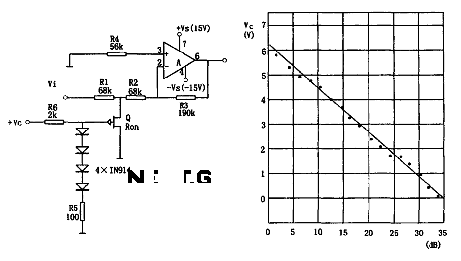
The voltage-controlled gain amplifier utilizes a FET gate voltage and the drain-source resistance (RSD) to approximate a logarithmic relationship. The integrated circuit chip LM307 is employed in the amplifier circuit with the inverting input configuration. In the circuit, RSD...
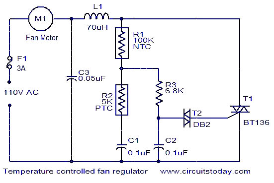
The function is designed to automatically control the speed of a fan based on the temperature. Components include a BT136 Triac, capacitor, resistor, relay, and fan motor. The circuit employs a temperature sensing mechanism to monitor ambient temperature levels. A...
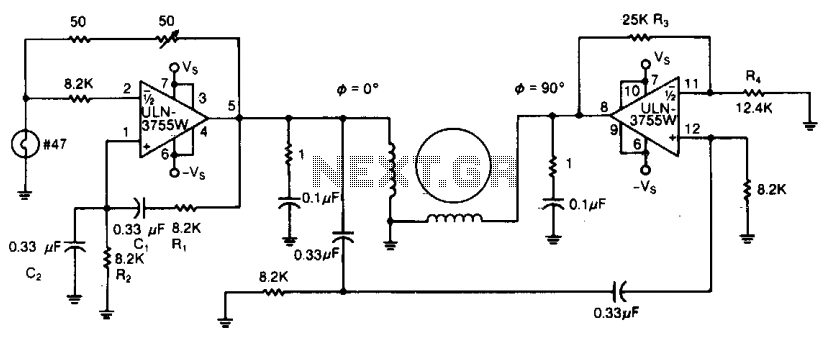
Due to its high amplification factor and integrated power-output stage, an integrated power operational amplifier serves as an effective driver for AC motors. One operational amplifier can be configured as an oscillator to generate the necessary AC signal. The...
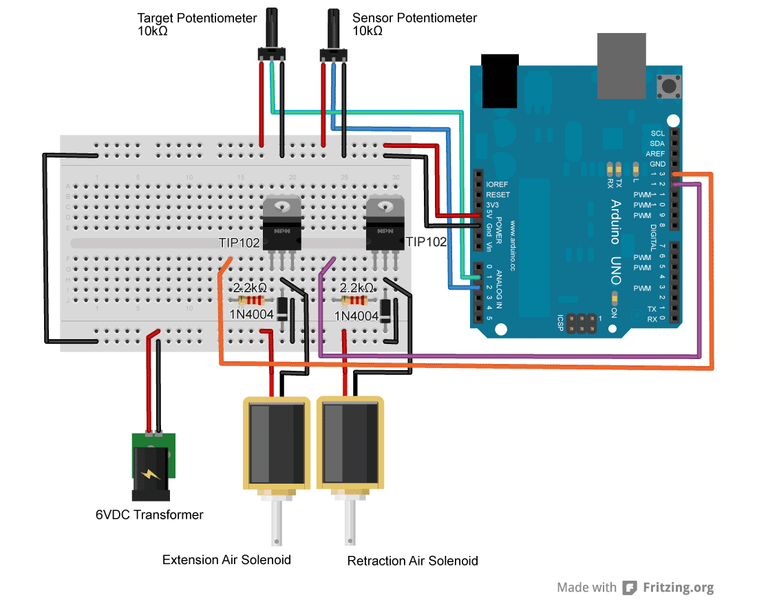
For an upcoming project, a pneumatic ram with a closed-loop control system was required to achieve precise positioning. Due to budget constraints, an off-the-shelf solution was not feasible, prompting the assembly of a custom system using an Arduino, a...
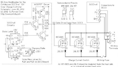
This circuit utilizes small switching transistors, with a maximum motor drive current limited to approximately 250 mA at 5V. Testing has been conducted across a voltage range from 3V to 21V, and with certain component modifications, it may be...