
2 Watt FM Transmitter

The described circuit is a classic example of an RF oscillator designed for FM transmission. The core of the circuit is the Hartley oscillator, which utilizes a tank circuit to generate oscillations at the desired frequency. The tank circuit consists of an inductor (L1) and a variable capacitor (trim cap), which together determine the oscillation frequency. The modulation process is achieved via the second transistor (T2), which acts as a variable capacitor due to its junction capacitance. By applying audio signals from the electret microphone through the first transistor's amplifier stage, the audio signal modulates the frequency of the oscillator.
The choice of using an electret microphone is significant because it provides a compact and efficient means of capturing audio signals. The use of P1 as a volume control allows for user adjustment of the microphone's sensitivity, enabling better audio input levels for modulation.
Construction of the coil is critical for achieving the desired RF performance. The recommended use of a thin gauge enamel magnet wire ensures that the inductance remains small and manageable, which is essential for higher frequency applications. The specified method of forming the coil around an ink tube allows for consistent coil geometry, which is crucial in minimizing inductance variability. The number of turns, typically between 8 to 12, directly affects the inductance and thus the tuning characteristics of the oscillator.
Overall, this circuit design presents a straightforward approach to building a compact RF oscillator for FM applications, suitable for various experimental and educational purposes. Proper attention to component selection and construction techniques will enhance the performance and reliability of the oscillator.The circuit is basically a radio frequency (RF) oscillator that operates around 100 MHz. Audio picked up and amplified by the electret microphone is fed into the audio amplifier stage built around the first transistor. Output from the collector is fed into the base of the second transistor where it modulates the resonant frequency of the tank circ
uit (L1 coil and the trimcap) by varying the junction capacitance of the transistor. Junction capacitance is a function of the potential difference applied to the base of the transistor T2. The tank circuit is connected in a Hartley oscillator circuit. P1 act as condenser microphone volume level. For FM, coil will be small. Use thin gauge enamel magnet wire. the diameter of coil will be a couple mm: use ink tube from pen to form, and try 8-12 turns. Small inductance coils make for much guess work. 🔗 External reference
Related Circuits
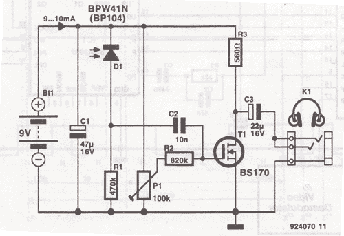
This wireless headphones transmitter ensures quality reception over a distance of 2 meters. The oscillator frequency ranges from 1750 kHz to 3500 kHz, and for the antenna, it... The wireless headphones transmitter operates within a frequency range of 1750 kHz...
The wireless FM transmitter circuit described here includes an additional RF power amplifier stage following the oscillator stage, which increases the power output to 200-250 mW. The wireless FM transmitter circuit functions by modulating audio signals onto a radio frequency...
This is an economical 150 Watt amplifier circuit that utilizes two complementary Darlington power transistors, TIP 142 and TIP 147. It is capable of delivering a robust 150 W RMS to a 4 Ohm speaker, offering significant audio output....
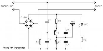
This circuit connects in series with a home phone line and transmits phone conversations through the FM band whenever the telephone handset is picked up. The transmitted signal can be tuned by any FM receiver. The circuit includes an...
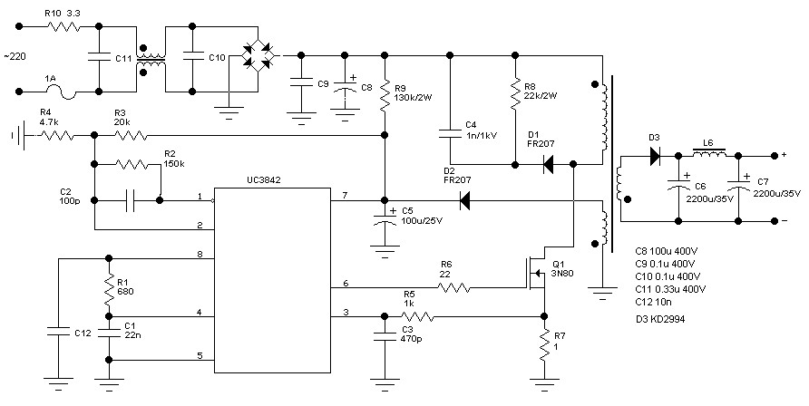
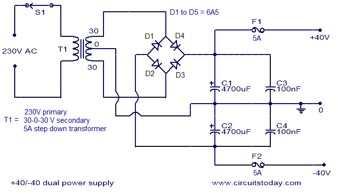
60 Watt Switching Power Supply. Visit the page for an explanation of the related circuit diagram. The 60 Watt Switching Power Supply is designed to convert an input voltage to a regulated output voltage while maintaining high efficiency and compact...
This watt-meter circuit has a measurement range of up to 1 kW. It can provide complete (X)(Y) functionality while utilizing only one transistor. The circuit is designed for operation with 117 Vac ± 50 Vac. Modifications can be made...