
20 amp output circuit

The circuit employs a combination of series and parallel capacitors to optimize performance based on load impedance. In low impedance scenarios, a series capacitor is preferred, while high impedance conditions benefit from the use of a parallel capacitor. The system is designed to operate within a 50-ohm framework, which is critical for effective antenna and coaxial cable integration.
Switch SW3 serves as a pivotal component in this setup, enabling the operator to either bypass the series capacitor entirely or augment the capacitance as required. This feature is particularly useful for fine-tuning the circuit to achieve optimal performance across a broad range of capacitance values, from 20pF to 900pF. The tuning methodology employed is akin to that of a pi network, which is characterized by a "dip and load" approach. This technique involves adjusting the plate current by manipulating the capacitors in a specific sequence to achieve the desired output.
Capacitor C4 is primarily responsible for the initial plate current dip, which is a critical step in the tuning process. After achieving the dip, the loading capacitance is progressively increased through capacitors C5, C6, and C7. This gradual adjustment allows for precise control over the operating plate current, ensuring that it remains within the desired range. The interaction among capacitors C4, C5, C6, and C7 is significant, as each capacitor influences the others, necessitating a careful and iterative tuning process.
Ultimately, the goal is to stabilize the plate current at approximately 150 mA. Under these conditions—specifically, with 500 VDC applied to the TZ-20 plates—the circuit is capable of delivering an input power of 75 watts. This design showcases the intricate balance between various components and their roles in achieving efficient circuit performance in RF applications.A series capacitor worked best for low impedance loads while a parallel capacitor was used to feed into high impedance loads. Today`s norm is a 50 ohm antenna antenna/coax system requiring a series capacitor. loading adjustment. With SW3 I can switch out the series capacitor all together or add in additional capacitance to give me a total
range from about 20pF to 900pF. Tune up becomes very much like a pi network "dip and load". With SW3 and C5 set for minimum capacitance the plate current is dipped using C4. After dipping, the loading capacitance is increased using C5, C6 and C7 into the range of operating plate current and then the current redipped using C4. C4, C5, C6 and C7 interact so this process must be repeated until the last C4 adjustment puts the plate current where it needs to be for full output.
in my case about 150 mA. 500 VDC on the TZ-20 plates at 150 mA gives me 75 watts input. 🔗 External reference
Related Circuits
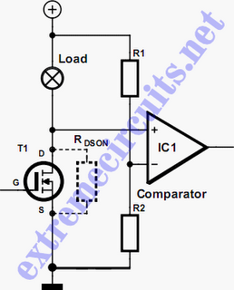
In applications where a MOSFET is used to switch a load, it is relatively straightforward to incorporate short-circuit or overload protection. This can be achieved by utilizing the internal resistance RDS(ON), which generates a voltage drop proportional to the...
Ultrasonic atomizer circuit: How to generate an atomized water mist using ultrasonic sound waves. The ultrasonic atomizer circuit is designed to produce a fine mist of water by utilizing ultrasonic sound waves. This process involves the conversion of electrical energy...

Signals always involve at least two paths to complete a circuit. For instance, when electrons travel down the center lead of a guitar cable, an equivalent number return on the shield. The shaft of the plug connects to ground...
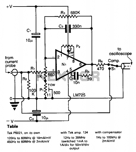
A clamp-on current probe, such as the Tektronix P6021, is an effective tool for displaying current waveforms on an oscilloscope. However, its low-frequency response is somewhat limited, as indicated in the accompanying table. The more sensitive range of the...
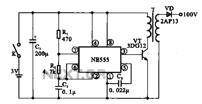
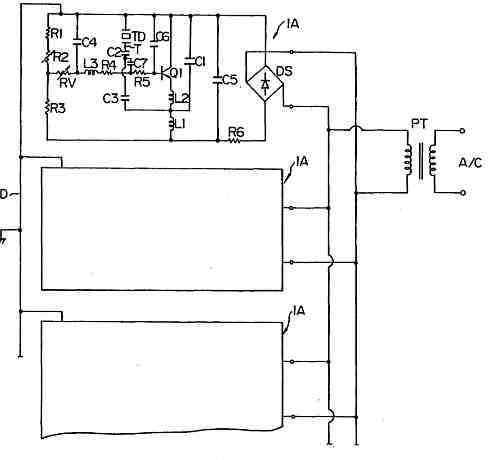
This circuit illustrates a simple boost converter, which is powered by an oscillating signal generated by the NE555 timer. The signal is amplified through a VT transistor to drive a booster transformer. This step-up transformer increases the oscillating signal,...
Short circuits or broken PCB tracks can be easily identified using a multimeter; however, this tool may yield inaccurate results when testing the efficiency of a transistor or diode unless the component is unsoldered and removed from the PCB....